765
Technical Committee 103 /
Comité technique 103
,
⋅
⋅
1
,
⋅
⋅
⋅ ||
where
is the horizontal translational coordinate,
is the
horizontal force,
is the force in the associated vertical spring,
0.7
is the interface friction coefficient,
is the initial
stiffness and
is the representative foundation area covered
by the spring set.
The soil spring is defined from the same principle, but
independent of the vertical force:
,
⋅
⋅
1
,
⋅ ||
where
is a maximum shear stress.
Unloading and reloading is defined with hysteretic
behaviour. Since material damping is embedded in the
hysteretic behaviour, the dashpot only includes radiation
damping.
3.3
Hysteretic behaviour
All nonlinear springs are defined with hysteretic behaviour
according to the extended Masing rule, as described by Kramer
(1996).
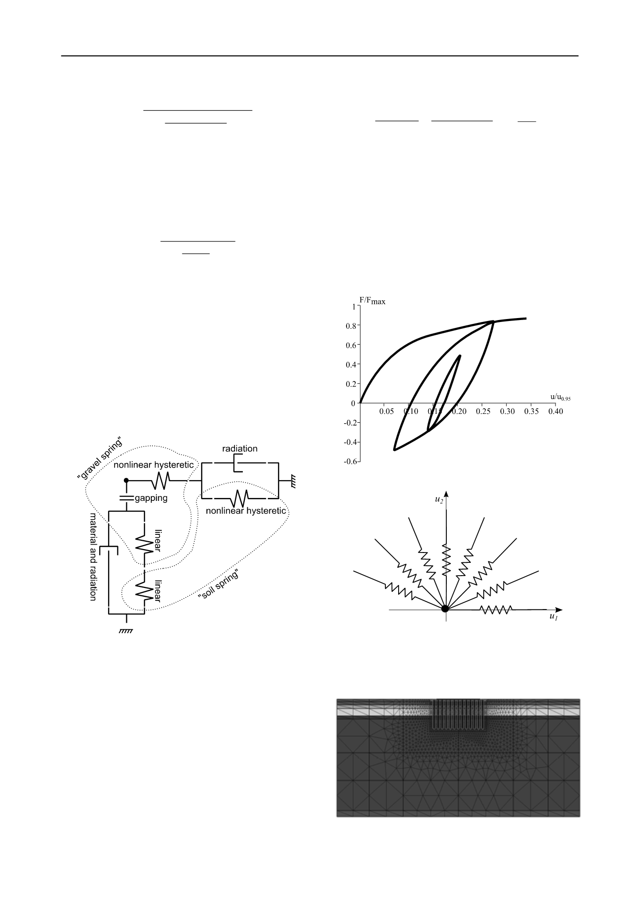
An example of a hysteretic force-displacement curve is
shown in Figure 6.
Figure 5. Detailed view of each set of distributed springs. The dotted
loops show which elements are referred to as "gravel" and "soil"
behaviour.
3.4
Two-dimensional generalisation
The terms "vertical" and "horizontal" are used in the above for
springs and dashpots. While the vertical component involves no
further complications, the horizontal springs and dashpots shall,
however, be defined in the two horizontal dimensions. Since the
springs are nonlinear and hysteretic, this definition is non-
trivial.
The intended behaviour is obtained by actually applying in
total eight non-linear springs, distributed in the horizontal plane.
The concept is illustrated in Figure 7. The full angular space is
covered by symmetry in the spring definitions.
4 DETERMINATION OF PARAMETERS
4.1
Vertical gravel springs
The linear vertical gravel springs are determined as
⋅
105 MPa ⋅
3 m 35
⋅
⋅
where
and
are the thickness and the oedometer
modulus of the gravel bed. The oedometer modulus of 105 MPa
corresponds to the unloading stiffness measured in plate loading
tests of a comparable gravel bed.
4.2
Vertical soil springs
The linear vertical soil springs are calibrated such that the
behaviour of the tower foundations under a vertical load plus an
overturning moment in IBDAS matches that in a 2D plane
strain finite element model in Plaxis. The Plaxis model
considers both the gravel bed and the pile-reinforced subsoil
and is shown in Figure 8.
Figure 6. Hysteretic curve following Masing behaviour.
Figure 7. Discretized lateral F-u supports around each spring location,
each representing a 1D non-linear F-u relation for their space angle.
Figure 8. 2D Plaxis model, north tower.


