764
Proceedings of the 18
th
International Conference on Soil Mechanics and Geotechnical Engineering, Paris 2013
displacement time histories are applied in the seismic analyses.
The springs, dashpots and gapping elements have been derived
to provide a realistic, best-estimate representation of the
nonlinear soil-structure interaction during seismic events based
on unfactored material parameters.
2 TOWER FOUNDATIONS
The concept of limiting the seismic forces in the superstructure
by seismic base isolation of the bridge piers (FIB 2007) has
previously been used e.g. for the Rion-Antirion cable-stayed
bridge in Greece (Yang et al. 2001). The pier foundations were
placed on a gravel bed on soil improved with steel pile
inclusions, which are not connected to the foundations. Such a
solution allows for rocking, gapping and sliding of the
foundations. The same concept is used for the tower foundations
of the Izmit Bay Bridge.
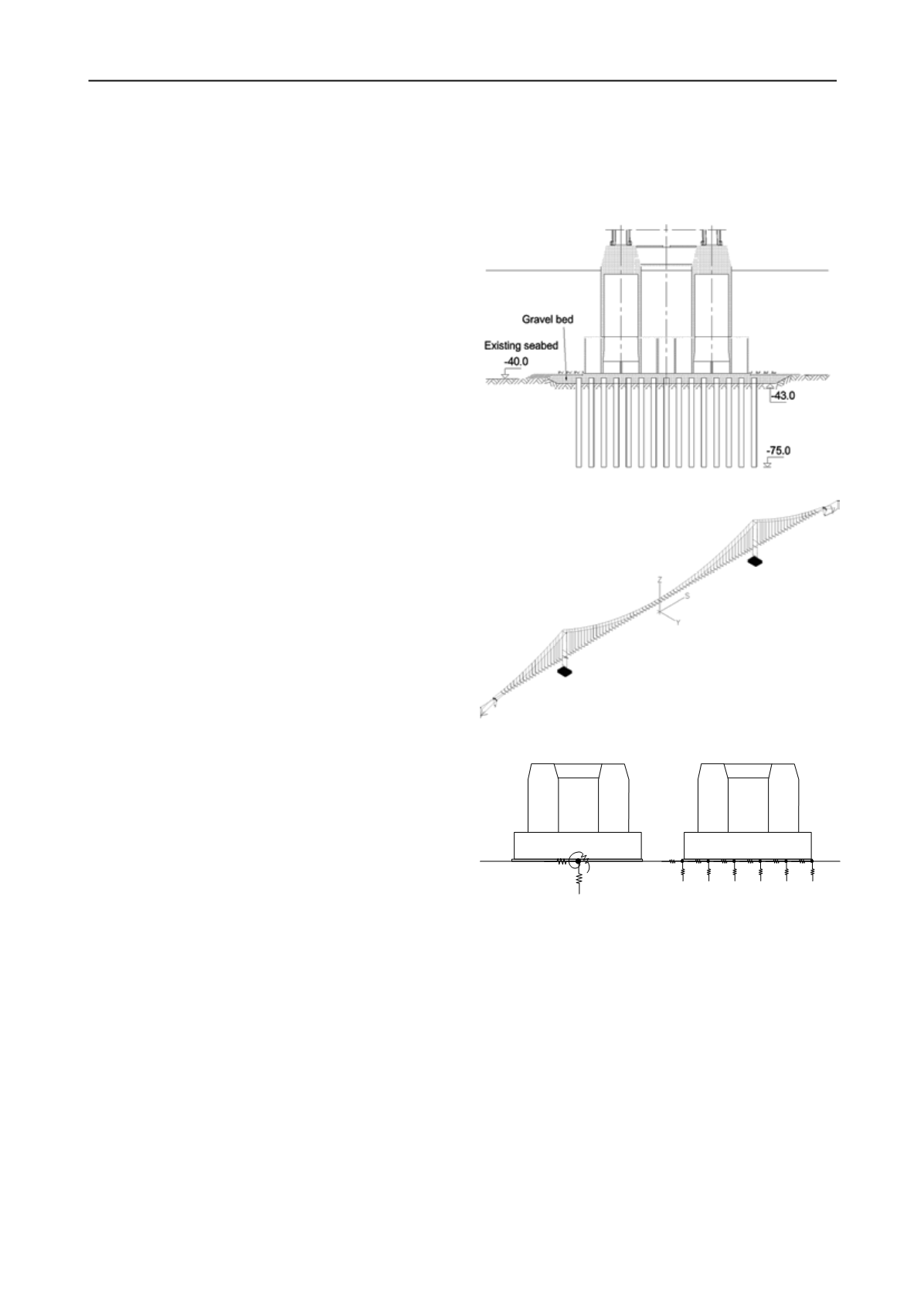
The tower foundation caissons with a 54 x 67 m footprint
area are placed on a 3 m thick gravel bed, as shown in Figure 2.
13 x 15 rows of 2.0 m diameter and 34.25 m long driven steel
pile inclusions with wall thicknesses of 20 to 25 mm are used to
improve the subsoil under each caisson in order to provide
sufficient bearing capacity and limit the permanent
displacements within the subsoil under ship impact and seismic
events.
The ground conditions of the tower foundations are
characterised by sand and clay layers. The spacing of the pile
inclusions is 5 m in both directions. The pile inclusions stop
within the gravel bed, 0.75 m below the gravel bed surface.
3 MODELLING CONCEPT
In order to model the above mentioned foundation
characteristics in sufficient detail, a finite element
representation of the soil-foundation interface is developed and
implemented in COWI's FE-software for bridges, IBDAS
(Sørensen et al. 1990). Special features for this soil-foundation
model include:
-
Use of distributed foundation supports
-
Horizontal response coupled to vertical force
-
Non-linear, hysteretic spring formulation
-
Two-dimensional generalisation of springs
3.1
Global model
The global finite element model is established in IBDAS (cf.
Figure 3). The entire bridge is described in a single model,
capable of non-linear construction phase modelling, response
spectrum analysis as well as fully non-linear time domain
calculations.
3.2
Distributed supports
In typical applications for global modelling, the soil-structure
interface of a caisson may be represented by a single-point
support stiffness matrix, see e.g. (Lam et al. 2007).
The principle is shown to the left in Figure 4. By modelling
the interface as single-point support, the foundation bottom
must be modelled as a rigid structure, which implies that no
stresses inside the concrete caisson are calculated directly.
In order to generate such stresses directly during time
domain analyses, and to provide a detailed modelling of the
nonlinear behaviour under combined loading, it has been
decided to use distributed springs, as sketched to the right in
Figure 4.
In Figure 4, the springs are shown as single sets of springs,
for simplicity. Actually, for each spring-supported part of the
foundation area, a full set of horizontal and vertical springs and
dashpots is assigned, as sketched in Figure 5.
As a sufficiently accurate approximation, all sets of
distributed springs are defined identical, with no variation with
respect to the location below the foundation base plate. The
discretization of the distributed supports was investigated, and it
has been found that a 13-by-15 grid provided sufficient
resolution and accuracy.
Figure 2. Tower foundation vertical section.
Figure 3. IBDAS global finite element model of the bridge.
Figure 4. Principle of "single-point support" (left) and "distributed
supports" (right).
3.2.1
Vertical elements
The vertical elements consist of two linear springs coupled in
series, a dashpot and a gapping element, cf. Figure 5. The
purpose of having two springs is to make it possible to
distinguish between the response in the gravel bed and in the
reinforced soil below the gravel bed. Since both springs are
linear, both material and radiation damping are included in the
dashpot. It has been evaluated that the linear approach provides
a very reasonable approximation to the push-over response, cf.
Section 4.2.
3.2.2
Horizontal elements
The horizontal elements consist of two non-linear springs, cf.
Figure 5. The backbone curve for the gravel spring is defined as
a function of the vertical force measured at the gapping element,
by the expression:


