771
Technical Committee 103 /
Comité technique 103
3.2
Analysis stages
The analysis procedure includes the next stages:
a) Calculation of the initial stress state generated by self-
weigh and the piezometric conditions.
b) Calculation of the stress state generated by the
construction of the existing metro line. This stage considers the
excavations, and casting of the walls and slabs (bottom and
cover) at the same time.
c) Calculation of the stress state and vertical displacements
generated by the excavations at both sides of the intersection. In
this stage, it is considered that the excavations are made
simultaneously with the walls and the slabs (bottom and cover),
so that, the horizontal support is present only at the level of the
slabs.
Figure 5. 3D Finite differences model
d) Calculations of the stress state and displacements
generated by the excavation of the new tunnel. In this stage the
tunnel support (primary lining) is also installed.
e) Calculation of the stress state and displacements
generated by the excavation and construction of the runways of
the new tunnel.
4 ANALYSIS RESULTS
4.1
Excavations at sides of the intersection (stage c)
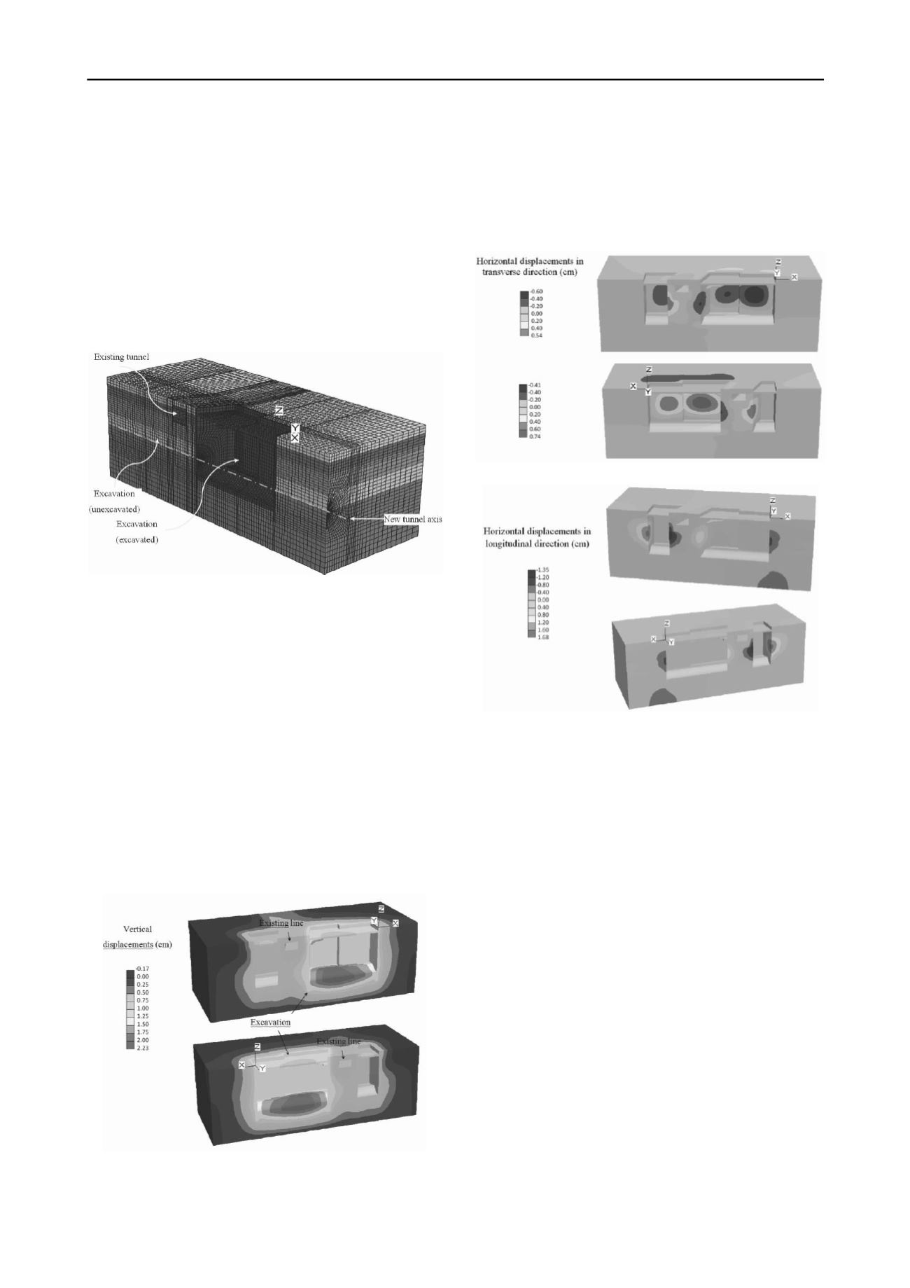
Figure 6 shows the vertical displacements computed in the stage
c. The maximum expansion occurs at the bottom of the
excavation, in the east side of the intersection with a magnitude
of 2.2 cm. This expansion is in agreement with the low
compressibility soils that are found at the bottom of the
excavation.
Figure 6. Vertical displacements after stage c
Figure 7 shows the horizontal displacements in the
transversal direction to the new tunnel axis after stage c. The
maximum horizontal displacements occur in the walls of the
excavation and have a magnitude of about 0.7 cm. Similarly,
figure 8 shows the horizontal displacements along the
longitudinal direction of the new tunnel axis after stage c. The
maximum displacements are between 1.4 and 1.7 cm and occur
in the walls of the excavation, in the west side of the
intersection.
Figure 7. Horizontal displacements in transverse direction (stage c)
Figure 8. Horizontal displacements in longitudinal direction (stage c)
4.2
Excavation and construction of the new tunnel line
(stage d)
Figure 9 shows the vertical and horizontal displacements
computed after analysis stage d, in which it can be observed the
following:
•
Close to the existing metro line, vertical expansions of
about 0.3 cm are generated. In the intersection zone, the tunnel
crown settles 0.3 cm while the bottom expands 0.6 cm.
•
Nearby the existing metro line, the maximum horizontal
displacement in the transverse direction to the new tunnel axis is
about 0.4 cm, and points towards the new tunnel axis.
On the other hand, due to the construction of the new line
outside the excavations, and in the intersection zone, the
following effects occur:
•
The new tunnel crown settles 0.4 cm and the bottom
expands 1.5 cm.
•
The maximum horizontal displacement in the transverse
direction to the new tunnel is 0.8 cm, and tends to open the
sides of the tunnel.
•
The maximum horizontal displacement in the
longitudinal direction is 0.1 cm, and tends to push towards the
center of the excavations. The computed horizontal
displacements are small, which shows that the excavations walls
and soil-cement improvement work efficiently to reduce such
movements. Likewise, the expansions are small due to the low
compressibility of the soil at the bottom of the excavations.


