772
Proceedings of the 18
th
International Conference on Soil Mechanics and Geotechnical Engineering, Paris 2013
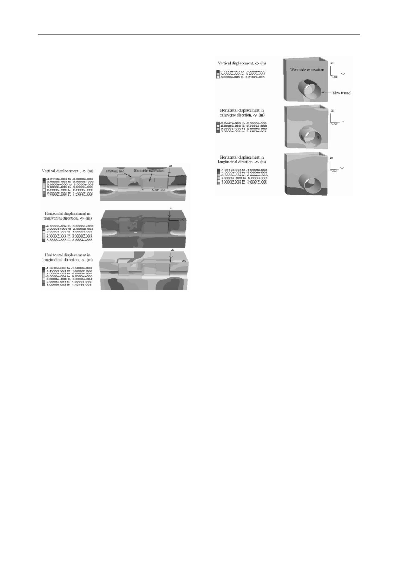
In order to understand the intersection behavior, Figure 10
shows the vertical and horizontal displacements in the new
tunnel at the intersection zone, which shows the following:
•
The maximum expansion in the new tunnel bottom is
0.5 cm, while the tunnel crown settles 0.1 cm. Thus, the tunnel
lining tends to move towards the tunnel axis 0.6 cm.
•
The maximum displacements in transverse direction to
the new tunnel are about 0.2 cm and occur at both sides of the
tunnel.
•
The maximum displacements in longitudinal direction
are of 0.05 cm and occur in the tunnel bottom, in opposite
direction respect to the tunnel crown, and also interact with the
excavation wall at the west side of the intersection.
Figure 9. Vertical and horizontal displacement after stage d
4.3
Excavation and construction of the runways of the new
tunnel line (stage e)
From the vertical and horizontal displacements computed after
analysis stage e, the following is observed:
•
The maximum expansion in the proximity of the new
tunnel is about 0.05 cm, and at the bottom of the runways is of
0.1 cm.
•
The maximum horizontal displacement in transverse
direction to the new tunnel is 0.1 cm.
•
The maximum horizontal displacement in longitudinal
direction around the tunnel and the runways is 0.4 cm and close
to the existing line is about 0.2 cm.
These results show that the construction of the runways will
not affect the behavior of the intersection.
Figure 10. Vertical and horizontal displacement after stage d in the
intersection zone.
5 CONCLUSIONS
Regarding the excavations at the sides of the intersection
(stage c), it can be concluded that both horizontal displacements
are small, and thus, the excavation will be adequately supported
by the excavation walls, and it will not pose any risk to the
future stability of the structure. With respect to the excavation
and construction of the new tunnel, it was found that overall, the
excavation and construction of the new tunnel will not affect the
existing one. In addition, the numerical study also shows that
the excavations walls and the soil-cement improvement
efficiently reduce the movements of the tunnel lines.
6 REFERENCES
Manuel Melis Maynar, and Luis Medina Rodriguez. 2005. Predicted
versus measured soil movements induced by shield tunnelling in
the Madrid Metro extension.
Can. Geotech
. J. 42: 1160–1172.
M. Migliazza, M. Chiorboli, G.P. Giani. 2009. Comparison of analytical
method, 3D finite element model with experimental subsidence
measurements resulting from the extension of the Milan
underground.
Journal of Computers and Geotechnics
36. 113–124.
RCDF. 2004.
Mexico City Building Code
Itasca Consulting Group. 2009.
FLAC3D, Fast Lagrangian Analysis of
Continua in 3 Dimensions, User’s Guide
. Minneapolis, Minnesota,
USA.


