770
Proceedings of the 18
th
International Conference on Soil Mechanics and Geotechnical Engineering, Paris 2013
one area to the other one underneath the existing station. A soil-
cement improvement was used in the entrance and exit of the
intersection. After the new tunnel was completed, two runways
were built at both sides of the tunnel for operating purposes. A
plan view and a cross section of the intersection are shown in
Figures 2 and 3 respectively.
Figure 2. Plan view of the intersection
BOTTOMSLAB
MILANWALL
SOIL-CEMENT
IMPROVEMENT
METALLIC
FRAMES
SOIL-CEMENT
IMPROVEMENT
EXISTING
METRO
LINE
CONCRETERING
NEWMETRO
LINE
EXCAVATION
EXCAVATION
Figure 3. Cross section of the intersection
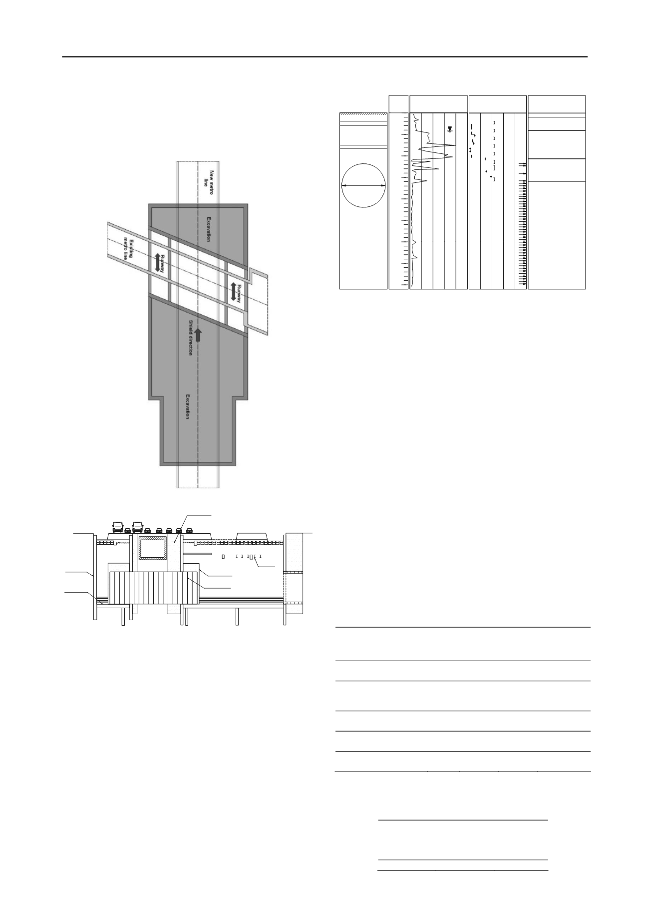
2 SOIL CONDITIONS
Typical subsoil conditions found at the site are presented in
Figure 4. The top layer is a 1 m thick manmade fill of sandy
clay and gravel. Underlying this fill a 3 m thick layer of very
soft to soft olive-brown sandy clay is found, with water contents
ranging around 50%, and standard penetration test, SPT, blow
counts around 1. This layer rests on top of a 6.75 m thick very
soft to soft olive and olive-brown clay layer with volcanic glass
and roots, with water contents going from 75% and 400%, and
SPT blow counts ranging from 1 to 5. This stratum is underlain
by a 5 m thick, medium to firm olive-gray and brown clay layer,
with fine sand lenses, and water contents between 10% and
250%, and SPT blow counts between 14 and over 50. Finally,
below this layer and until the maximum explored depth, a very
dense clayed sand with gravels, exhibiting water contents
between 20% and 60%, and blow counts over 50, is found. The
water table is located 4.5 m below ground surface.
10
200 300 400
Water content, %
20 30 40
Blow counts, N
ST
50/30
50/05
50/10
50/10
50/10
50/15
50/16
50/10
50/15
50/30
50/15
50/15
50/10
50/05
50/05
50/07
50/08
50/10
50/17
50/07
50/12
50/10
50/11
50/10
50/07
50/09
50/05
50/07
50/10
50/15
50/10
50/08
50/05
50/05
50/10
50/15
50/15
50/15
50/15
50/15
50/05
50/15
100
50/12
50/15
Filling.Gray sandy claywith gravel.
Soft olive-brown sandy clay.
Very soft to soft olive and
olive-brown clay with
volcanic glass and roots.
Description
Medium to firm olive-gray
and brown clay with fine
sand lenses.
Very compact clayed
sand and hard sandy clay
with gravel.
5
10
15
20
25
30
35
40
Deep,
m
New line
Existing
line
10.18
Ground level
ST
ST
ST
ST
ST
ST
ST
Water table
ST = Shelby tube
Figure 4. Ground conditions found at the site
3 NUMERICAL MODELING
3.1
Description of the model
The analysis of the intersection behavior was carried out using
the computer software FLAC
3D
[4], which is based on the finite
differences technique. This software allows analyzing stress and
strain states in three dimensions generated by loading and
unloading process in elasto-plastic materials. The implemented
model for the analysis is shown in Figure 5, it is comprised by
271,530 zones. In this figure, it can be seen also the location of
the existing tunnel, one of the excavations at the side of the
intersection, and the location of the new tunnel. The base of the
model was considered fixed in the three degrees of freedom and
the vertical faces, which limit the model, were fixed for
horizontal displacements but free to move vertically. The
geomaterials were modeled assuming an elasto-plastic behavior
with a Mohr-Coulomb failure criterion. The material properties
of the soil and reinforce concrete elements are summarized in
table 3.1 and table 3.2 respectively. The primary lining and
other structural elements were modeled as linear elastic.
Table 1. Soil properties used in the analysis
Material
Mohr-Coulomb
parameters
E
c
[kPa]
-
[kPa]
Manmade Fill
5
28
0.35
4500
Soft clay
12
25
0.28
3100
Very Soft clay
10
25
0.28
1800
Medium clay
25
30
0.30
7400
Very dense sandy clay
60
40
0.30
17000
= Poisson Ratio, E = Elastic Modulus
Table 2. Concrete parameters used in the analysis
Compression
strength at
28 days, f’
c
(kPa)
Elastic
Modulus , E
(MPa)
Poisson
ratio, ν
29420
17000
0.20
epth,
m


