754
Proceedings of the 18
th
International Conference on Soil Mechanics and Geotechnical Engineering, Paris 2013
5. CONCLUSION
3D numerical analysis is proposed to simulate the dynamic
behavior of a soil-pile system observed in dynamic centrifuge
tests(Yoo et al. 2012). Calibration and verification were then
carried out, to validate the applicability of the proposed
modeling methodology.
(1) Calibration of the proposed model is performed for the case
of a pile with a diameter of 100cm and wall thickness of 4cm.
Both in the centrifuge test and numerical model, resonance
occurs at the same frequency (1Hz), and peak bending moments
obtained from the proposed model agree well with those from
the centrifuge test.
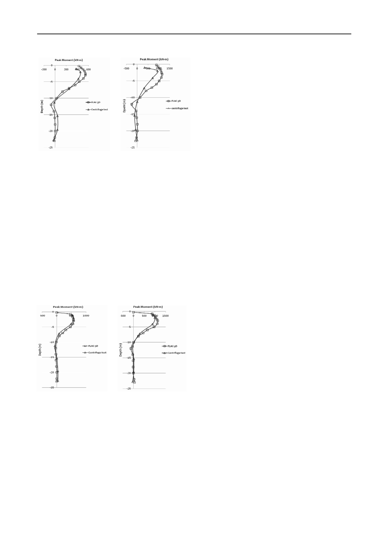
(a) Input acceleration : 0.13g (b) Input acceleration : 0.25g
Fig. 8 Peak bending moment along the pile (Nisqually)
4.1.2 Response to a real earthquake event
The analysis for real earthquake events, which is meaningful in
practice, was performed, to validate the modeling method
proposed in this study. In this stage, the acceleration record of
the Nisqually earthquake (2001) was used for the input motion.
The peak moment profiles along the pile, as obtained by
centrifuge test and numerical simulation, are shown in Fig. 8.
As the base input acceleration increases, the response increases,
both in the centrifuge test and FLAC-3D. These results are
consistent with the results for the sinusoidal wave. Also, it can
be seen that the results obtained from the numerical model agree
reasonably well with the values recorded during the centrifuge
test; and the average discrepancy was within 15%.
(2) Applicability of the proposed model is verified for the case
of a pile with a diameter of 72cm, and wall thickness of 4cm.
The peak bending moment profile obtained from numerical
simulation well predicts the centrifuge test, and the discrepancy
between the measured and computed values is within 10%.
Therefore, it can be concluded that the numerical model
proposed in this study has the ability to simulate the dynamic
behavior of a soil-pile system under various input conditions.
Also, it will be able to be applied to the practical seismic design
of pile foundations for various conditions.
6. ACKNOWLEDGEMENTS
This work was supported by the SNU SIR Group of the
BK21 Research Program funded by the Ministry of
Education, Science and Technology.
7. REFERENCES
Boulanger, R.W. and Curras, C.J. 1999. Seismic Soil-Pile-Structure
4.2 Verification of the numerical model
Interaction Experiments and Analyses. Journal of Geotechnical and
Another case of the centrifuge test with a pile diameter of 72cm
Geoenvironmental Engineering, Vol.125, No. 9, pp. 750-759
Dobry, R. and Gazetas, G. 1988. Simple method for dynamic stiffness
and damping of floating pile groups. Geotechnique,38, 557-574.
Hardin, B. O. 1978. The nature of stress-strain behaviour of soils.
Earthquake engineering and soil dynamics, 1, 3-90.
Iai, S., Tobita, T. and Nakahara, T. 2005. Generalised scaling relations
for dynamic centrifuge test. Geotechnique,55(5), 355-362.
Itasca Consulting Group, Inc. 2002. FLAC3D(Fast Lagrangian Analysis
of Continua in 3Dimensions) User's Guide, Minnesota, USA.
Kaynia, A. M. and Kausel, E. 1982. Dynamic behavior of pile groups.
2nd International Conference On Numerical Methods in Offshore
Piling, Texas University, Austin, 509-532.
Kim S H, Kwon S Y, Kim M M, Han J T. 2012. 3D Numerical
Simulation of a Soil-Pile System Under Dynamic Loading. Marine
Geosources & Geotechnology. 30(4), 347-361.
Klar, A. and Frydman, S. 2002. Three-Dimensional Analysis of Lateral
Pile Response using Two-Dimensional Explicit Numerical Scheme.
Journal of Geotechnical and Geoenvironmental Engineering, 128 (9),
775-784
(a) Input acceleration : 0.13g (b) Input acceleration : 0.25g
Fig. 9 Peak bending moment along the pile (1Hz)
and pile wall thickness of 4cm at the prototype scale, is
modeled by the proposed modeling method, and a comparison
between the measured value and computed value was performed,
to verify the applicability of the proposed modeling method.
The peak moment profiles along the pile, obtained by centrifuge
test and numerical simulation, are shown in Fig. 9. The peak
bending moment profile obtained from numerical simulation
well predicts the centrifuge test, and the discrepancy between
the measured and computed values is within 10%. Therefore, it
can be concluded that the numerical model proposed in this
study has the ability to simulate the dynamic behavior of a soil-
pile system under various input conditions. Also, it will be able
to be applied to the practical seismic design of pile foundations
for various conditions.
Makris, N. and Gazetas, G. 1992. Dynamic pile-soil-pile interaction.
Part II: Lateral and seismic response. Earthquake Engineering and
Structural Dynamics, 21, 145-162.
Martin, G.R. and Chen, C. Y. 2005. Response of piles due to
lateral slope movement. Computers and Structures, Vol. 83, pp.
588-598
Taylor, R.N. 1995. Centrifuge in modelling: principles and scale effects.
GeotechnicalCentrifugeTechnology, 19-33
Yang E K. (2009). Evaluation of dynamic p-y curves for a pile in sand
from 1g shaking table tests. Ph.D. Dissertation, Seoul National
University.
Yoo M T, Han J T, Choi J I, Kim M M. 2012. Comparison of Lateral
Pile Behavior under Static and Dynamic Loading by Centrifuge Tests.
GeoCongress 2012. Oakland, CA, USA. 2048-2057


