749
Technical Committee 103 /
Comité technique 103
The essence of this method consists in concentration of
bending ability in discrete points. If the beam with bending
stiffness
E
1
I
1
is decomposed to the parts of length
Δl
the
bending stiffness at each point is
Δl IEr
/
11
.
(14)
The stiffness matrix for a beam with free ends
...
... 6 4 1 0 0
... 4 6 4 1 0
... 1 4 6 4 1
... 0 1 4 5 2
... 0 0 1 2 1
2
Δl
r K
.
(15)
5 CALCULATION OF BEAMS ON ELASTIC HALF-
SPACE
5.1
Concentrated load
The beam with plan dimensions 3×51 resting on the half-space
with unit concentrated force in the centerpoint was calculated .
Different beam stiffness values were considered; they were
described by the flexibility index (Gorbunov-Posadov
e.a. 1984):
11
2
3
)
1(2
IE
bEa
t
,
(16)
where
a
,
b
= half-length and half-breadth of the beam. Contact
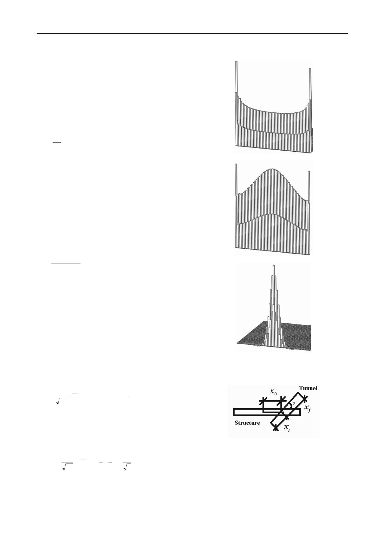
zone boundary element decomposition was to unit squares. The
calculation results are shown on Figure. 1 and demonstrate the
effect of the beam stiffness in the longitudinal direction: the
pressure diagram shows changes from the rigid punch type for
t
= 10
–3
to alternating-sign type for
t
= 10
3
; for the intermediate
value
t
= 1 there are maxima both in the center of the beam
under the concentrated load and at the ends.
5.2
Concentrated load
For the calculation of bending of the beam that models an
elongated structure we accept formula (Attewell e.a. 1986) for
the settlement of the of the soil surface due to tunnelling with
the account for the position of the tunnel face (the structure
back effect on the structure is neglected):
I
x
G
I
x G e
I
V w
f
i
I
s
2
2
2
2
*ˆ
,
(17)
where
V
s
= volume of lost ground; 2
I
= width of the settlement
trough between the inflection points; ξ, η = coordinates (ξ axis =
projection of the tunnel axis on the soil surface, η axis is
perpendicular to ξ axis );
x
i
and
x
f
— ξ coordinates of the tunnel
initial and final points;
2
erf
2
1
2
1
2
1
2
d e
G
.
(18)
t
= 10
–3
t
= 1
t
= 10
3
Figure 1. Contact pressure under the footing of the beam on the half-
space with concentrated load for flexibility index
t
= 10
–3
; 1; 10
3
. The
part of the diagram symmetrical about the axis of the structure is not
shown.
Figure 2. Relative position of the tunnel and the structure.
Consider different tunnel positions relative to the existing
elongated structure, influenced by the tunnelling. The structure
is the same as in the previous example; flexibility index is 1.
The half-width of the settlement trough is taken equal to the
half-length of the structure. The general layout scheme of the
structure and the tunnel with the corresponding parameters,
describing their mutual position is shown on the Figure 2.


