3237
Technical Committee 307 /
Comité technique 307
Following backfilling of the craters, earthworks were
undertaken to reshape the surface of the various benches after
which conventional fill placement was carried out to achieve
design levels. In areas, this required the placement of up to 2 m
of compacted fill which was placed under Level 1 geotechnical
control to the requirements of Australian Standard AS3798 –
1996. As a result of the success of the dynamic compaction
phase (which provided a solid base), the undertaking of
additional earthworks was relatively straightforward with a
compaction requirement of 100% of standard maximum dry
density achieved in all fill areas. Fill materials included the use
of coal washery rejects, a mining by-product from the coal
washing process that is obtained at low cost (typical transport
only) but has very good civil engineering properties for use as
general fill and no negative environmental impacts.
5.3
Site Monitoring
Construction works for the ground consolidation contract were
undertaken in accordance with a Construction Environment
Management Plan (CEMP). The key objective of the CEMP
was to develop a monitory programme for regulatory
compliance and early detection of any significant environmental
or community impacts.
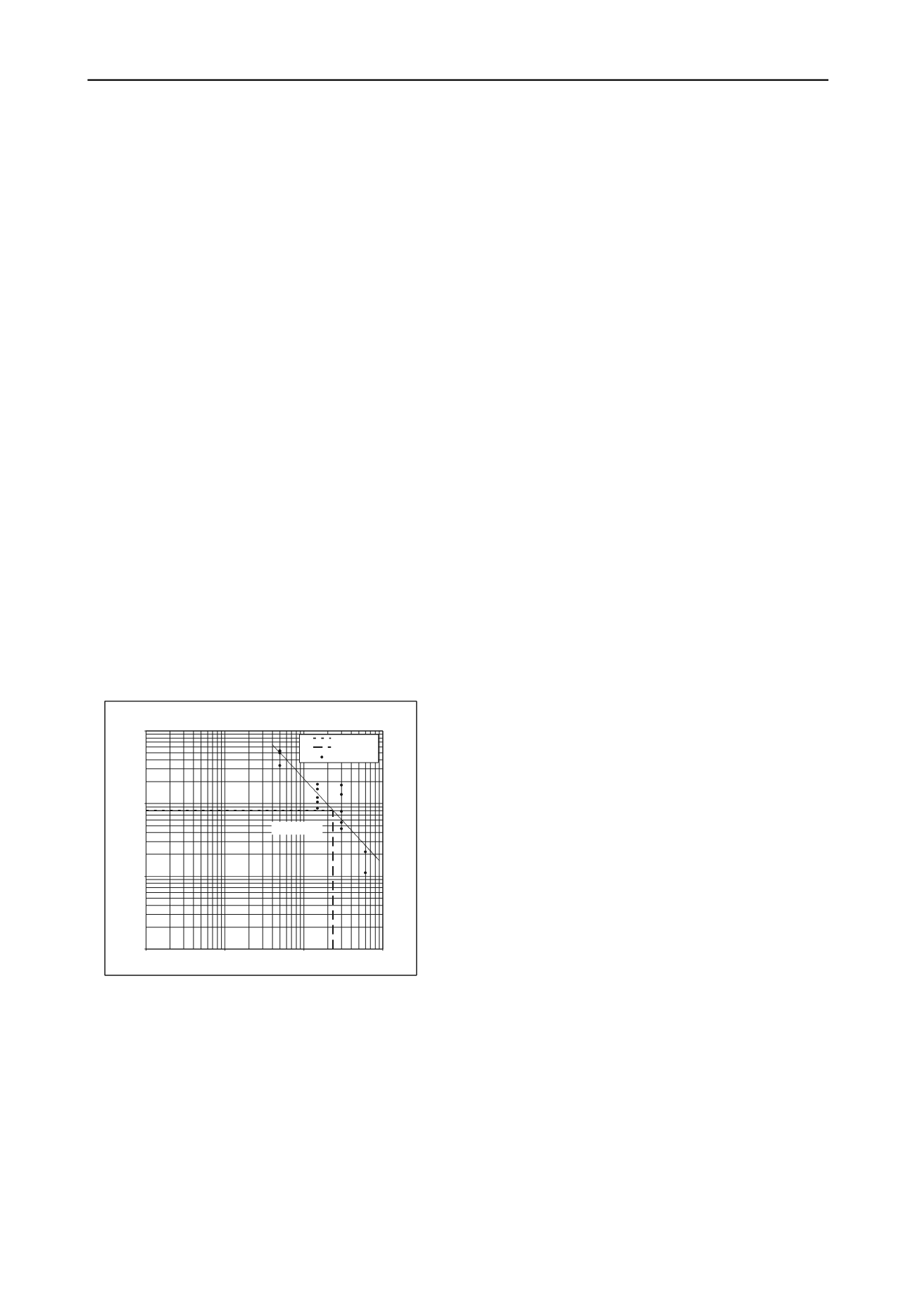
Given the potential impacts due to dynamic compaction
being carried out on the site and the presence of buildings on
neighbouring properties, vibration trials were undertaken prior
to commencement of compaction. An attenuation graph was
prepared as shown in Figure 4 with a boundary buffer distance
of 25 m nominated for a proposed vibration limit of 8 mm/sec
(sector sum and component peak particle velocity). Texcel
Vibration Monitors were installed for continuous data recording
(one of which was in a neighbouring building) and adopting the
buffer distances established by the trial, only nine exceedances
were recorded during the 6 month construction period. No
complaints were received from neighbouring properties.
Figure 4: Dynamic Compaction Vibration Attenuation Graph
Whilst noise was considered to be the other major
environmental impact that could cause community concern
during compaction activities, monitoring over the 6 month
period recorded a total of only 32 readings above the
performance criteria of 75 dBA. Odour was primarily of
concern during the initial excavation phase and was managed by
minimising waste exposure time. Similarly, dust was managed
by the implementation of good construction practices on site.
Leachate and groundwater was monitored regularly with all
outflow to the pre-determined requirements. Whilst results
were typical of those expected from a landfill site, manganese
and ammonia were flagged as elements of concern.
The obvious area of concern in all landfill projects is landfill
gas (LFG). Methane, carbon dioxide and oxygen levels were
monitored both inside and outside the landfill boundary as well
as within site buildings. Daily monitory of landfill was
undertaken using a GA2000 Gas Meter. Both surface and well
measurements were taken as well as barometric pressure and
lower explosive limit. Peak methane levels of up to 97% were
recorded in wells in the landfill footprint, with levels generally
in the range of 14 – 50%. Monitoring in wells adjacent to the
landfill boundary was generally below threshold levels or 0%
methane. Surface and enclosed space monitoring showed that
LFG was not considered to be an issue at any time during the
works.]
6 FUTURE WORKS AND BUILDING DESIGN
6.1
Civil works, services and stormwater drainage
All civil and building services (eg sewer, water, stormwater,
electrical, gas) have been designed such that they will not need
to penetrate the capping layer of the landfill. All service
trenches and other works that require excavation (eg
landscaping) will be within ‘clean’ material and limited to
excavation depths of 2m. Earthworks associated with site
reshaping will require construction of retaining walls up to 7m
high. The walls have been designed as reinforced earth
structures able to accommodate ground settlements of 300mm.
6.2
Foundations
The main advantage of dynamically compacting the landfill is
that long term settlement of the landfill (post building
construction) will be significantly reduced, but not eliminated
(Thom 1998). As such, footing design for buildings located
within the landfill footprint will be for driven steel piles
founding in the underlying latite bedrock. Flexible aprons will
be needed between the buildings (which will experience
negligible settlement) and adjoining carparks, walkways and
recreation areas (which will experience ongoing settlement).
Whilst raft slabs may be feasible for some lightweight single
story buildings, preliminary analysis has indicated that a 1 m
thick reinforced earth raft will be needed to provide uniform
bearing and to equalise the longer term settlements so that
differential movements will be within acceptable limits.
Dynamic Compaction Vibration Attenuation Graph: Nan Tien CampusSite
y = 333.39x
-1.1794
0.1
1.0
10.0
100.0
0.1
1.0
10.0
100.0
Source-ReceiverDistance (m)
Peak ParticleVelocity (mm/s)
Allowed Limit
BufferDistance
TrialData: PPVi
6.3
Leachate Control and Gas Drainage
Leachate collection drains will be installed across the site and
directed to the leachate treatment system. The current options
for leachate collection include disposal to sewer, reinjection,
spray or drip irrigation, removal by contractor, ammonia
stripping, constructed wet lands and membrane bio reactor.
The primary elements of the environmental design are
capping profile, methane drainage and leachate control. The
requirement of the site capping is twofold; firstly – physical
separation by covering contaminated materials and secondly –
prevention of infiltration to the substrate, thereby minimising
leachate recharge and mobilisation and upward migration of
methane. Historically landfill capping systems have included a
0.5 m clay cap however this system alone was not considered
intrinsically safe at this site in areas underneath buildings or
pavements where piles will breach the cap and gas can
accumulate in enclosed spaces.
The preliminary design for the capping consists of HDPE,
GCL, geotextile fabric, 300 mm gravel gas drainage layer and a
reinforcing geotextile, underlain by the existing waste, refer to
Figure 5 below. Undercrofts will be constructed where possible
to allow for suspension of services and cross-ventilation. In
areas outside of the buildings an additional 1 m layer of clean
fill material to further protect the cap from stormwater and root
infiltration, drying out, cracking and accidental breaches will be
installed. The preliminary design requires the landfill cap to


