3232
Proceedings of the 18
th
International Conference on Soil Mechanics and Geotechnical Engineering, Paris 2013
Figure 1 shows part of their results. Seawater and fresh water
were tested with Portland cement and powdered blast furnace
slag (PBFS) as additives. When fresh water was used, cement
was more effective than PBFS in solidifying GBFS. But when
seawater was used, PBFS was more effective than cement.
Using seawater and PBFS was the most effective combination.
3
ISSUES REGARDING APPLYING THE GBFS
SOLIDIFICATION ACCELERATION METHOD IN THE
FIELD
There are several issues to consider when determining the most
appropriate mixture of GBFS and PBFS for accelerating GBFS
solidification: (1) the material can separate during construction,
(2) it may separate after construction because of water flow (3)
separation of the mixture is likely to affect how the GBFS
solidifies, (4) the flow of pore water can affect solidification,
and (5) GBFS may solidify differently when the pore water
changes from sea water to fresh water (Kikuchi et al. 2010).
In the present study, we examine issues (1) to (5). First, we
present experimental results regarding issues (2), (3), and (4).
We then explain a way to prevent issue (1), and finally consider
issue (5).
3.1
Possibility of material separation after construction
The physical properties of the GBFS used were
s
= 2.845
g/cm
3
,
dmin
= 1.175 g/cm
3
,
dmax
= 1.508 g/cm
3
, D
15
= 0.28 mm,
and D
50
= 0.38 mm. The physical properties of the PBFS used
were
s
= 2.890 g/cm
3
, with 5000 to 7000 cm
2
/g of specific
surface area. Artificial seawater was used as pore water.
The diameter of the PBFS was about 4
m assuming
spherical particles with no small holes. Thus, the GBFS and
PBFS may separate when the mixture is poured onto the seabed.
The ratio of D
15
for GBFS to D
85
for PBFS is more than 50.
This ratio is an indicator of the possibility of material separation
due to water flow through the material (Ishihara 2001).
We conducted experiments on the separation of the PBFS
from the mixture. In this series of experiments, specimens with
two layers were prepared. The lower layer of the specimen was
a mixture of GBFS with 20% PBFS by weight. The upper layer
was only GBFS. The relative density of each layer was 50%.
Water flowed from the bottom of the specimen with a
hydraulic gradient of from 10 to 40. This test was conducted in
a triaxial apparatus at a confining pressure of 50 kN/m
2
to
prevent boiling. The outlet velocity of the water at a hydraulic
gradient of 40 was 120 m/day. The total outlet water volume
from the specimen was 6 times the void volume of the specimen.
Figure 2 shows close-up X-ray CT images of the boundary
between the layers of the specimen, where the contrast reflects
the density of the material. Comparing the images before and
after water flow, small differences can be observed. This means
that although there may be a little separation when the peak
velocity of the water flow is 120 m/day, complete separation of
the material does not occur under these conditions.
In practice, the water flow velocity in GBFS used as backfill
for gravity quay walls is around several m/day. Thus, GBFS and
PBFS will never separate after construction.
Before water flow After water flow of 120m/day
Figure 2. Close-up X-ray CT images at mid-height of the specimen.
3.2
Solidification of GBFS after material separation
The effect of material separation on the solidification
characteristics of the material is examined in this section.
The GBFS and PBFS used here were the same as those used
in section 3.1. The relative densities of the specimens were 50%.
The pore water used was artificial sea water. In each specimen,
7.5% PBFS by weight was added to the GBFS. We tested four
experimental mixing regimes: (1) GBFS and PBFS were mixed
homogeneously (HMT), (2) PBFS was mixed with GBFS, then
artificial sea water was added to achieve a 10% water content
ratio and the mixture was cured in air for a week (prior
homogeneous mixing treatment or PHMT), (3) One PBFS layer
was sandwiched between two layers of GBFS, and (4) Two
PBFS layers were sandwiched between three GBFS layers.
Each specimen was saturated with artificial sea water and
sealed, then cured for a designated period at a constant
temperature of 20 degrees centigrade. Each specimen’s
unconfined compression strength was measured after the
designated curing period.
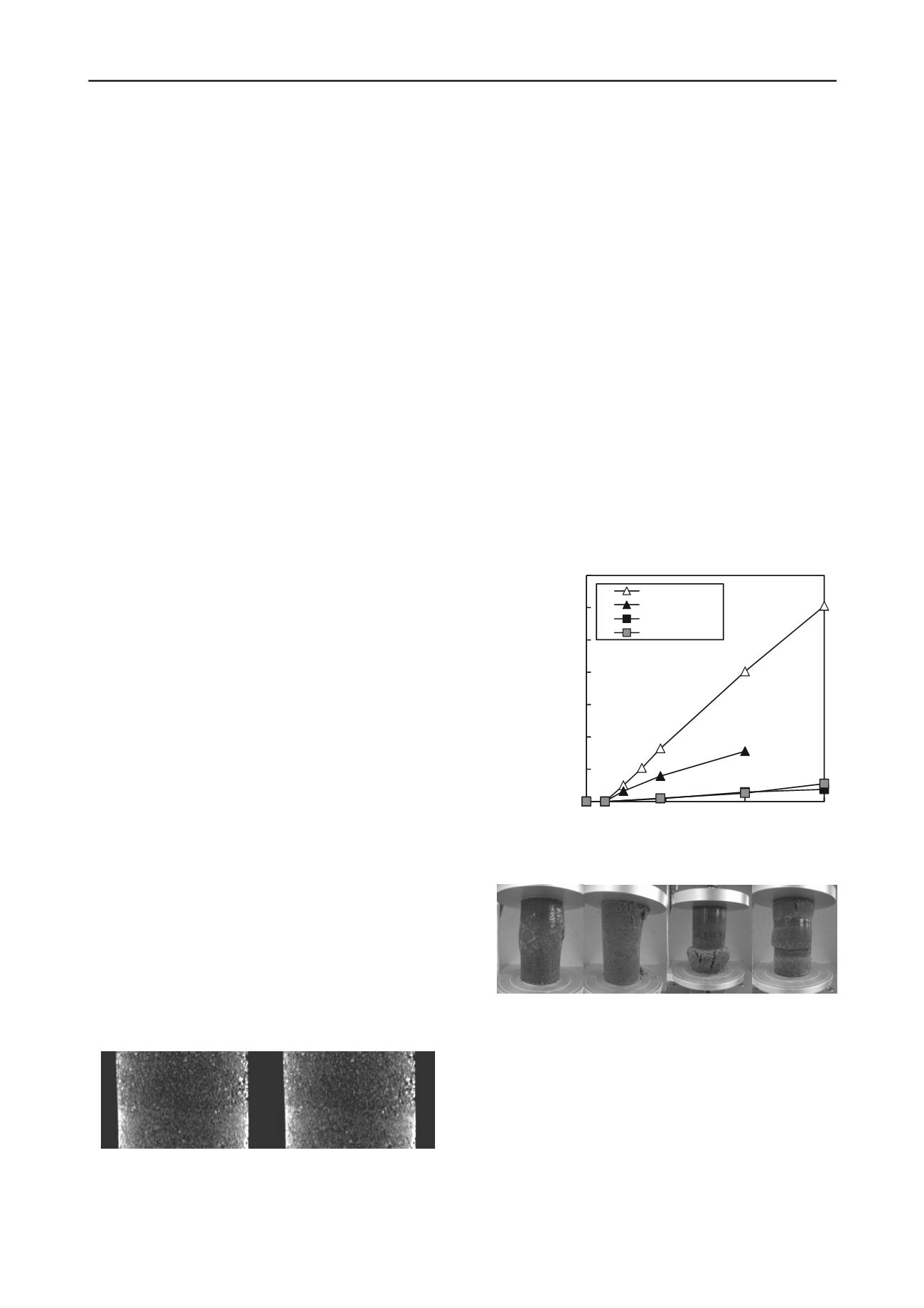
Figure 3 shows the relationship between the curing duration
and unconfined strength. The unconfined compression strengths
using HMT and PHMT exceeded 200 kN/m
2
after 14 days of
curing. These strengths increased as the curing time lengthened.
When the materials were separated, such as in cases (3) and (4),
the unconfined compression strengths were very low. Figure 4
shows examples of the failure states for each case.
0
500
1000
1500
2000
2500
3000
3500
0
30
60
Unconfined compression strength
q
u
(kN/m
2
)
Curing time (days)
90
HMT
PHMT
One layer
Two layers
Figure 3. Change of unconfined compression strength with curing time.
(a) HMT (b) PHMT (c) One layer (d) Two layers
Figure 4. Failure modes of specimens in each mixing regime
These results show the importance of thoroughly mixing the
GBFS and PBFS in accelerating the solidification of the GBFS.
3.3
Solidification of GBFS underground with flowing water
In previous research, movement of pore water has been shown
to prevent GBFS solidification (Kitayama 2003). In this section,
we examine how pore water flow effects GBFS solidification.
In this series of experiments, two water flow conditions and two
mixing conditions were tested.
We used the same GBFS and PBFS as in section 3.1, and the
HMT (1) and PHMT (2) mixing regimes from section 3.2.


