3236
Proceedings of the 18
th
International Conference on Soil Mechanics and Geotechnical Engineering, Paris 2013
4 SITE INVESTIGATION AND RESULTS
4.1
Geotechnical
Investigations to establish a geotechnical model of the site
included 103 test pits to depths of up to 5 m, 14 cored boreholes
to depths of up to 12 m and the installation of 8 standpipe
piezometers. In summary, the natural geological profile of the
site comprised topsoil over residual clays with latite and
sandstone bedrock (generally of medium to high strength)
below depths of 1 – 1.5 m. The profile of the landfill included a
coal washery rejects (CWR) and clay capping layer some 0.5 –
3.5 m in thickness (but generally less than 1 m) with the depth
of the waste in the order of 4 – 12 m.
The landfill waste was interbedded with CWR and clays, as
was expected given the conventional operation of a putrescible
waste facility. The density of the landfill was generally loose
with some denser sections as reflected by standard penetration
test “N” values in the range 2 – 30. Perched water tables were
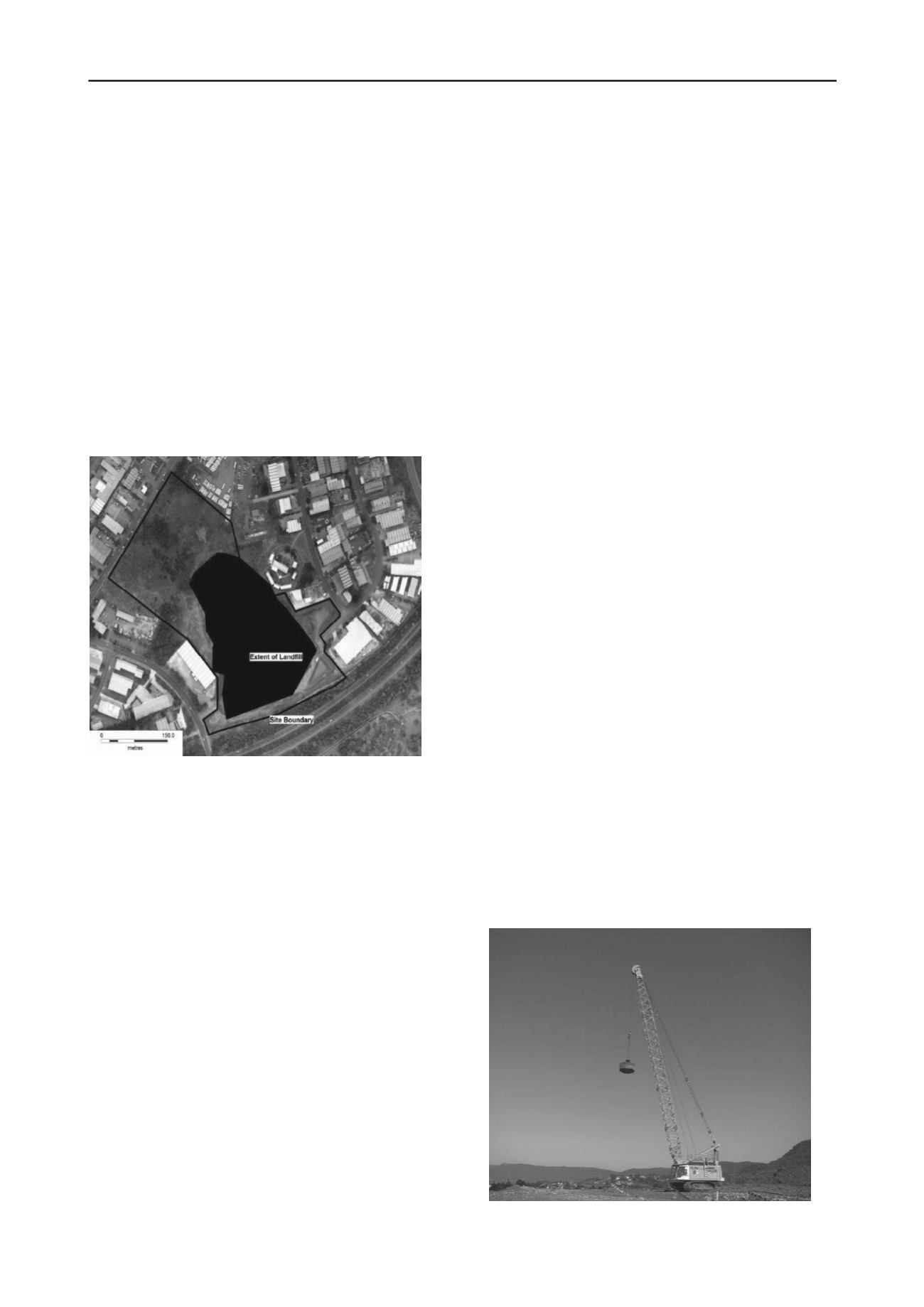
also present. The extent of the landfill is shown in Figure 1.
Figure 1. Extent of landfill.
4.2
Environmental (soil, water, air, noise)
180 test locations were investigated across the site, most of
which were in the landfill footprint. Contaminant
concentrations were compared to the NSW DECC (2006)
Health based Investigation levels. Within the soils, elevated
levels of manganese and hydrocarbon (C10 – C36) were
recorded. Testing of groundwater indicated elevated levels of
iron, manganese, ammonia, nitrate and total phosphorus, typical
of levels and contaminants found in landfill leachate. Methane,
hydrogen sulphate and carbon dioxide were recorded in the gas
monitoring wells with the methane levels within either the
“explosive” range or exceeding the “explosive limits” and in a
range that may cause asphyxiation.
In the areas outside the landfill footprint, no environmental
concerns were recorded apart from random dumping of
uncontrolled fill which was managed by conventional
construction practices.
5 GROUND CONSOLIDATION WORKS
Site preparation was completed in March 2011 and included
construction of a temporary leachate collection system,
reshaping and benching of most of the site, dynamically
compacting the landfill and undertaking of controlled
earthworks to achieve design levels. Monitoring of air quality,
noise, vibration levels and leachate was ongoing during the
works.
5.1
Civil Design and Leachate Control
During initial site works, the expectation was that a relatively
significant quantity of leachate would discharge from the
landfill cell which would reduce after dynamic compaction.
The reduced quantities were expected to be treated and
managed long term by a membrane bio-reactor (prior to
discharge off site or re-use on site). As the bio-reactor could
not be sized to cater for the high loads during site preparation
works, a 2ML leachate pond was constructed downslope of the
landfill cell. Leachate was fed into the pond via a 2 m
groundwater cut-off trench installed around the toe and flanks
of the landfill cell. Once in the pond, leachate was then pumped
through a treatment system consisting of pumps, sand filters,
activated carbon filters and an automatic sampler prior to
discharge into the sewer system via a Trade Waste Agreement
with Sydney Water.
The leachate pond was designed to not only suit its purpose
during dynamic compaction and site preparation (i.e. as a
leachate pond), but to also double as an on-site detention (OSD)
pond during the life of the Institute. This OSD pond assists
with long-term management of stormwater on the site. The
HDPE liner installed in the leachate pond during dynamic
compaction was removed and the pond readily transformed for
the OSD purpose. This saved having to build two very similar
structures twice.
5.2
Dynamic Compaction
In order to improve the density of the landfill (and thus to
improve longer term performance by limiting primary
compression and secondary consolidation following progressive
waste decomposition), dynamic compaction was selected as the
appropriate method. The equipment (shown in Figure 2)
included a 120 tonne crawler crane dropping a 25 tonne pounder
from a height of (nominally) 20 m. Compaction was carried out
in two phases. Following placement of a coarse “compaction
layer” to provide stability for the crane, the primary phase
comprised multiple drops of the concrete pounder (typically 3 –
4) on a 6 m x 6 m grid with the craters backfilled as the
compaction proceeded. The final (or ironing) phase was carried
out using a pounder of similar mass but a larger footprint (5 –
9 m2) with a drop height adjusted to the pounder size and
compression achieved.
Using the methods of Hausmann (1990), an assessment was
made of the degree of ground improvement with surface
settlements of generally 1 – 2 m expected in the areas underlain
by the deeper landfill. The survey results following completion
of dynamic compaction and were predominantly within the
range 0.5 – 1.5 m, in line with expectations and generally 10 –
12% of overall landfill depth.
Figure 2. Dynamic Compaction Equipment.


