2976
Proceedings of the 18
th
International Conference on Soil Mechanics and Geotechnical Engineering, Paris 2013
was in the layer where stone columns were placed in a square
grid 2.8x2.8m. Therefore, instead of obtaining an increase in
module of compressibility due to soil improvement by stone
columns, we got a decrease with respect to the design values.
From there it follows that the compressibility of the CL/CH
layer was overestimated in the design. Other layers according to
the obtained measurement results were correctly determined in
the design in terms of the modules of compressibility.
Based on the calculated parameters of compressibility from
Model 1, a numerical model of finite elements was made in
Plaxis 2D-Model 2. The soil was described as an isotropic
elastoplastic material with linear elasticity properties until
failure and by Mohr-Coulomb strength law for stresses at
failure. A comparison of horizontal pile displacements before
superstructure execution was carried out through the model
obtained by back analysis. Also, the comparison of bending
moment diagrams obtained by back analyses and on the basis of
measured displacements was also carried out.
0
100
200
300
400
Displacment (mm)
-50
-40
-30
-20
-10
0
10
Elevation [m a.s.l.]
LEGEND
pilot A-inclinometer
pilot C - inclinometer
pilot D - inclinometer
pilot A - back analysis
pilot C - back analysis
pilot D - back analysis
-4000 -3000 -2000 -1000
0
1000 2000
Bending moment - pile D [kNm/m']
-50
-40
-30
-20
-10
0
10
Elevation [m a.s.l.]
LEGEND
inclinometer
model 2
Figure 12 Bending moments in pile D, on the basis of displacements in
vertical inclinometer and for back analyses model 2.
5 CONCLUSION
The paper aims to describe the design process and control of
execution of a demanding structure –coastal structure, which
takes into account soil-structure interaction.
The procedure was carried out iteratively through collaboration
of design teams of structural engineers and geotechnical
engineers.
The geotechnical model was made based on delivered loads and
design assumptions of soil parameters. Through the
geotechnical model and finite element method, the coefficients
of soil reaction were determined through soil pressure and
displacements. Ground reaction coefficients were delivered to
the designers of the structure. By means of such procedure in
several steps, through collaboration of design teams, soil-
structure interaction assumed in the design was obtained.
Verification of efficiency of planned works was performed
through geotechnical measurements described in the paper.
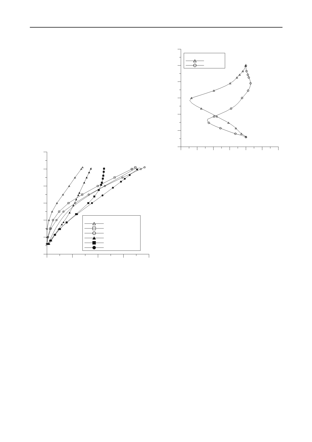
Figure 11 Horizontal displacements of piles A, B and C obtained by
measurements in horizontal inclinometer and by back analysis through
Model 2.
Figure 11 shows horizontal pile displacements during
construction, before construction of coastal structure.
Differences in horizontal displacements at the top of the piles
obtained by measurements and through model 2 are within
tolerance limits. The shapes of displacement curves do not
coincide, and therefore the distribution of internal forces is also
different. From Figure 11 it follows that the layers from -20 m
to -44 m are less compressible than in data obtained based on
back analyses through models 1 and 2.
Based on geotechnical measurements, back analysis of soil
parameters (Model 1) and the condition of internal forces and
displacements of the structure (Model 2) was performed.
In this paper, we wanted to point out that it is necessary to
perform back analyses during and after execution of demanding
structures on the basis of performed measurements and through
collaboration of structural and geotechnical engineers.
6 ACKNOWLEDGEMENTS
Figure 12 shows bending moments obtained on the basis of
measurements and back analyses through models 1 and 2 for
pile D (last pile landwards).Diagrams show the temporary phase
of bending moment before the construction of coastal structure.
Maximum bending moments appear in the case obtained on the
basis of measurements of horizontal displacements in
inclinometer.
The authors would like to give special thanks for collaboration
and support shown by Mr. Rene Lustig and
Mr.DarkoPavokovic, the designers of the coastal structure from
Rijekaprojekt.
7 REFERENCES (TNR 8)
Rocscience, 2009.
Settle 3D Version 1.0.,
Rocscience Inc. 31 Balsam
Ave., Toronto, Ontario, M4E 1B2, Canada
Brinkgreve R.B.J., Engin, E. and Swolfs W.M., 2012.
Plaxis 2D 2012
Plaxisbv P.O. Box 572, 2600 An Delft, Netherlands
Priebe HJ1995, The design of vibroreplacement,
Grounding
Engineering, December
, p. 31-37


