2974
Proceedings of the 18
th
International Conference on Soil Mechanics and Geotechnical Engineering, Paris 2013
0.00
-10.00
-20.00
-40.00
-30.00
ELEVATION [m a.s.l.]
SFs/ML
CL/CH
ML/SFs
G
CL/CH
c=0 kPa
=30°
Cu=20-40kPa
Cu=40-80kPa
c=10 kPa
=28°
c=0kPa
=40°
SPT correlation
Shear VaneTest
CPT
Consolidated UnrainedTest
Direct ShearTest
Consolidated UndrainedTest
Direct ShearTest
SPT correlation
-50.00
+10.00
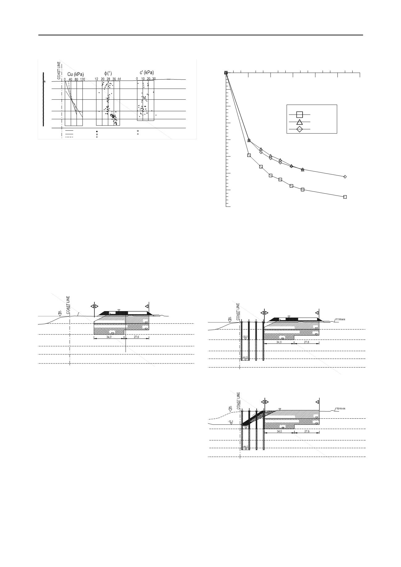
Figure 2 Geotechnical soil profile with performed in-situ exploratory
works and laboratory tests.
3 MEASURMENTS AND CONSTRUCTION PHASES
Terminal construction was divided into four main phases:
execution of vibrated stone columns and preloading in the
storage area, execution of piles from the coast on previously
prepared terrain, excavation and underwater embankments, and
construction of the coastal structure.
There are two zones of execution in stone columns: dense
(triangular grid 2x2m) and sparse improvement (square grid
2.8x2.8m). Dense soil improvement was carried out down to -
8m a.s.l. Sparse improvement was performed down to -15m
a.s.l. i.e. -20m a.s.l. in such a way that every other column of
dense improvement is extended down to the required depth. The
role of stone columns is to provide global stability, and
settlement reduction and acceleration.
Because of terminal construction dynamics, pre-loading of
storage areas was, due to limitations of material for preloading,
performed independent of phases, on the condition that they are
executed before the execution of coastal structure. Preloading
was executed in three segments (fields).
STORAGE AREA
STONE COLUMNS 2x2m
STONE COLUMNS 2.8x2.8m
-8 m a.s.l.
-20 m a.s.l.
-33 m a.s.l.
-42 m a.s.l.
-52 m a.s.l.
Cu=20-40kPa
Cu=40-80kPa
c=10 kPa
=28°
c=0 kPa
=40°
SFs/ML
CL/CH
ML/SFs
G
CL/CH
INCLINOMETER
DEFORMETER
COASTAL
CONSTRUCTION
TERRAIN
c=0 kPa
=30°
+5,55
+2,55
-20,0
-8,0
-15,0
PRELOADING
Figure 3 Construction phase I: improvement of foundation soil with
stone columns and pre-loading in the area of storage and traffic
surfaces.
Each construction phase was monitored through geotechnical
and geodetic measurements. Geotechnical measurements in the
area of storage and traffic surfaces consisted of measuring
vertical displacements by horizontal inclinometers, and
settlement measurements by layers using vertical deformeter
(see Figure 3). A net of geodetic points was placed on the top of
pre-load.
Pre-loading was performed in three fields, in such a way that
the material was transferred from one field to another.
Settlement of the first field was measured by horizontal
inclinometer and vertical deformeter, and with a net of geodetic
points 12x12 m. Measurements showed the settlement of 70 cm
in the period of 105 days, and they are shown on Figure 4. The
difference in settlement between the inclinometer and
deformeter is caused by the fact that the deformeter's reference
point is at 44 m and underneath it there are compressible layers
which could not be followed by the deformeter.
23/8/08 22/9/08 22/10/08 21/11/08 21/12/08 20/1/09 19/2/09
Date
800
700
600
500
400
300
200
100
0
Settlement (mm)
LEGEND
inclinometer
deformeter
back analysis
Figure 4.Inclinometer and deformeter settlement measurements together
with the settlement curve obtained by back analyses in the first field of
preloading.
The requirement for duration of preloading of 90 days was
obtained by analysing the consolidation curve. For the other two
fields, the same preloading duration requirement was set.
Settlement measurements in the second and third field were
performed on geodetic points. Measurements in the second field
have shown settlement of 30 cm, and in the third of 50 cm. The
reason for smaller measured settlement is longer time of placing
pre-loading, and the fact that the reference measurements were
performed only after preloading was completed.
Cu=20-40kPa
Cu=40-80kPa
c=10 kPa
=28°
c=0 kPa
=40°
SFs/ML
CL/CH
ML/SFs
G
CL/CH
STORAGE AREA
STONE COLUMNS 2x2m
STONE COLUMNS 2.8x2.8m
COASTAL
CONSTRUCTION
+5,55
+2,55
-8,0
PRELOADING
-20,0
-15,0
D
B A
C
c=0 kPa
=30°
-8 m a.s.l.
-20 m a.s.l.
-33 m a.s.l.
-42 m a.s.l.
-52 m a.s.l.
Figure 5 Construction phase II: execution of piles from the coast on
previously prepared terrain.
Cu=20-40kPa
Cu=40-80kPa
c=10kPa
=28°
c=0kPa
=40°
SFs/ML
CL/CH
ML/SFs
G
CL/CH
STORAGE AREA
STONE COLUMNS 2x2m
STONE COLUMNS 2.8x2.8m
COASTAL
CONSTRUCTION
+2,55
-8,0
-20,0
-15,0
D
B A
C
c=0kPa
=30°
-8 m a.s.l.
-20 m a.s.l.
-33 m a.s.l.
-42 m a.s.l.
-52 m a.s.l.
Figure 6 Construction phase III: undersea excavation and execution of
undersea embankment.
Geotechnical measurements on the coastal structure consisted of
measurements in vertical inclinometers-deformeters inside the
pile. Measuring equipment was installed in one profile, so that
one vertical inclinometer-deformeter was placed in tensile zones
of each of piles A and C. In pile D, two vertical inclinometers-
deformeters were placed –one in the compressive zone and the
other in the tensile zone. The tops of inclinometers-deformeters
were at the same time geodetic points, whose displacements
were geodetically followed. Inclinometer measurements showed


