2986
Proceedings of the 18
th
International Conference on Soil Mechanics and Geotechnical Engineering, Paris 2013
T
in
T
out
T
out
frost body
inner pipe (PE)
outer pipe (steel)
refrigerant
s
Q
e
Q
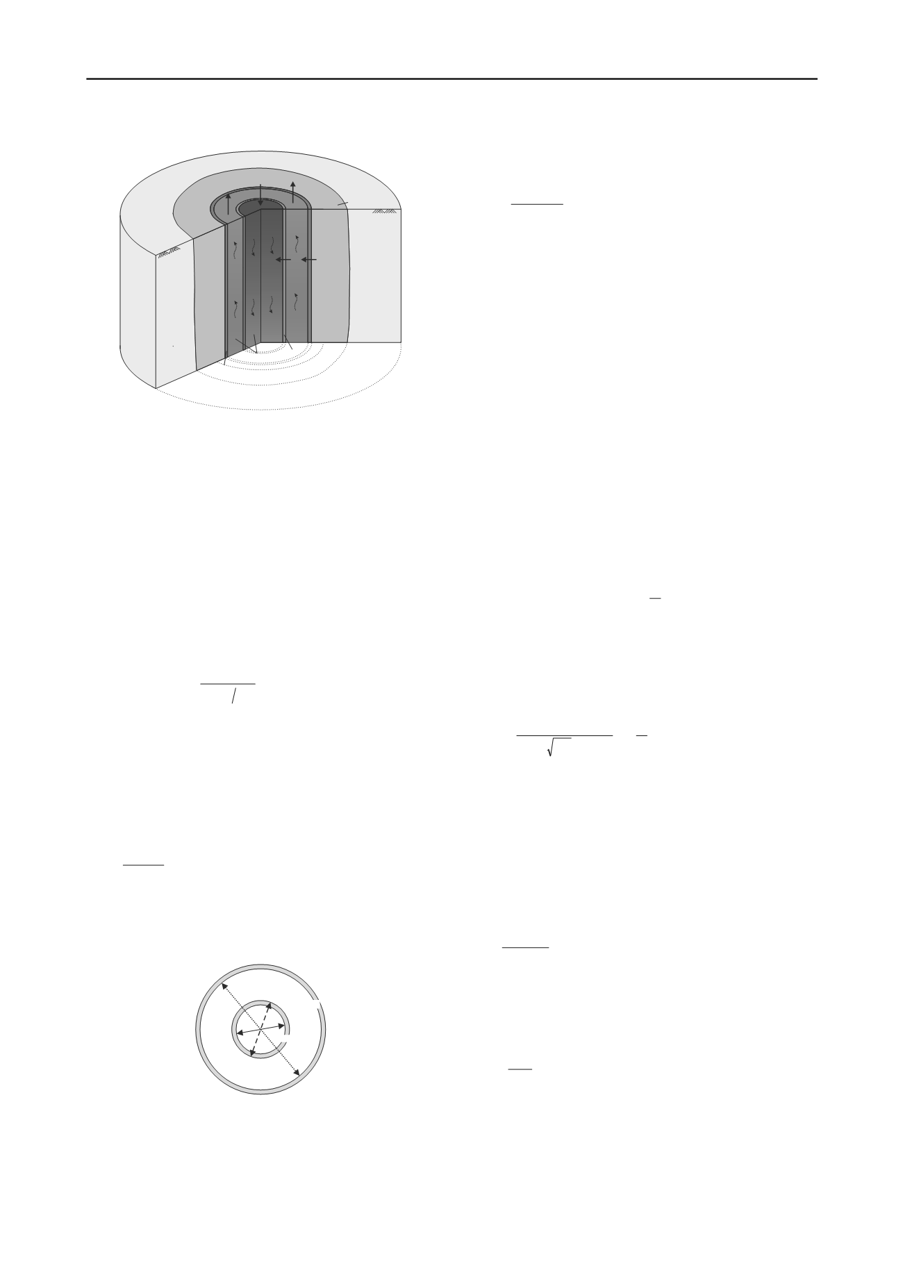
Figure 1. Freeze pipe in detail with occurring heat flow.
The heat flow
s
Q
between the soil and the outer freeze pipe
comprises conductive heat flow through the outer freeze pipe
and convective heat flow due to the flowing refrigerant. The
heat flow
e
between the down- and upstream via the inner
freeze pipe can be divided into two mechanisms. On the one
hand, conductive heat flow through the inner freeze pipe and on
the other hand convective heat flow both inside and outside the
inner freeze pipe. In case of a flowing refrigerant the vertical
heat transfer is dominated by advection which is already
considered in the horizontal heat flow. Therefore the vertical
conductive heat flow within the refrigerant is neglected.
Q
The heat transfer due to conduction can be determined by
using Fourier’s law. The conductive heat flow for a coaxial
freeze pipe for n conductive layers with the thermal
conductivity of the pipe material
i
[W/(mK)] results in:
n
i
i,in i,out
i
i
conduction
)r rln(
T
Q
1
2
(2)
The convective heat flow depends on the heat transfer
coefficient
i
[W/(m²K)]:
n
i
i i
convection
T r
Q
1
2
(3)
The heat transfer coefficient depends on the freeze pipe
geometry and the flow and material properties of the refrigerant.
As a function of the Nusselt number Nu the heat transfer
coefficient is defined as (Baehr and Stephan 2006):
hydrauli
F
d
Nu
(4)
with the thermal conductivity of the refrigerant
F
and the
hydraulic freeze pipe diameter d
hydraulic
. The hydraulic diameter
of the inner freeze pipe corresponds to its inner diameter
(see Figure 2).
d
in, outer pipe
d
in, inner pipe
d
out, inner pipe
Figure 2. Freeze pipe diameters to calculate hydraulic diameter.
The hydraulic diameter for the annular space is:
innerpip
,out
outerpipe
,in
hydraulic
d
d
d
(5)
The Nusselt number Nu depends on the flow type – laminar
or turbulent. To differ between the two flow types the Reynolds
number Re can be used, which depends on the refrigerant flow
velocity v
F
, the kinematic viscosity
and the hydraulic diameter
(VDI Heat Atlas 2010).
F
hydrauli
dv
Re
(6)
In the literature (Gnielinski 1995, VDI Heat Atlas 2010) it is
generally mentioned that a full developed turbulent fluid flow in
a pipe exists for Re > 10
4
. For Re < 2300 a laminar fluid flow
occurs. In the range of 2300 < Re < 10
4
the transition from
laminar to turbulent flow takes place. Furthermore, for all flow
types a distinction has to be made between a modified fluid
flow in the inlet area and a thermic and hydrodynamic fully
developed fluid flow behind this area (VDI Heat Atlas 2010).
Due to the spatial separation of the mechanical refrigeration
plant and the inlet area of the freeze pipes, it can be assumed
that the fluid flow reaching the inlet area is already fully
developed.
Moreover, the VDI Heat Atlas (2010) indicates the
differentiation between flow inside a pipe and in a concentric
annular gap. In this paper only the Nusselt numbers for the inner
freeze pipe are outlined. The equations for the calculation in the
annular gap can be found in VDI Heat Atlas (2010).
In general the Nusselt number depends on the Reynolds
number Re, the Prandtl number Pr, the inner pipe diameter d
i
and the length of the pipe l.Thus the Nusselt number in case of a
laminar flow and a constant heat flux density along the freeze
pipe can be calculated with:
313
31
/
/
3 3
60
9531 60 364 4
i
q,m
,
l
dPrRe
,
,
,
Nu
(7)
In case of a turbulent flow, there is no need for a
differentiation between the boundary conditions “constant wall
temperature” and “constant heat flux density” since the Nusselt
numbers are nearly equal. Thus the Nusselt number for
turbulent flow is defined as:
32
1
1 8 7121
8
i
/
m
l
d
Pr / ,
PrRe /
Nu
32
/
(8)
with:
2
10
51
81
, Re log ,
(9)
According to Gnielinski (1995) the following interpolation
function for the transition region between laminar and fully
turbulent flow should be used:
4
10
2300
1
,T,m
,L,m
m
Nu
Nu
Nu
(10)
with:
1 0
2300
10
2300
4
and
Re
Besides the Reynolds number the Prandtl number Pr is
needed for the calculation of the Nusselt number. The Prandtl
number characterizes the material properties of the refrigerant
(kinematic viscosity
, thermal conductivity
F
and volumetric
heat capacity c
F
) (Baehr and Stephan 2006):
F
F
c Pr
(11)
2.2
Numerical modeling
For a realistic calculation of all heat transfer mechanisms
described afore the use of numerical methods becomes
necessary. To avoid a very fine discretization which causes long
simulation times a seperate module “freezrefcap” for the
calculation of the heat transfer processes within the freeze pipe
has been developed in cooperation with Geophysica


