2904
Proceedings of the 18
th
International Conference on Soil Mechanics and Geotechnical Engineering, Paris 2013
End Bearing Resistance
Maximum mobilised resistance = 59MPa (ultimate end
bearing pressure not reached)
Little or no creep at an end bearing pressure of 38MPa
(this pressure was held for 30 minutes)
Shaft Resistance
Creep started at an average shaft resistance (over 5.5m
length) of 1.06MPa and was significant at 1.3MPa
The shaft response became “plastic” at a movement of
about 30mm, with a corresponding average shaft
resistance of 1.74MPa
The O-Cell test results confirmed the ultimate design values
adopted for design, and as in Case Study 1, demonstrated that
significantly higher serviceability end bearing pressure could be
considered in the design of rock socketed piles in Sydney rock.
If the presumptive end bearing pressure given in Table 2 for
Class I and II Sandstone was adopted, the serviceability end
bearing resistance would have been limited to 12MPa. The O-
Cell test clearly demonstrated that significantly higher
serviceability end bearing could be adopted, provided the base
of the rock socket is adequately cleaned. The pile construction
aspect of this case study to ensure adequate rock socket
roughness and base cleanliness is described in Sethi et al
(2012). However, it should also be stressed that under
serviceability loading, a large proportion of the applied load
may be carried by the pile shaft depending on the length to
diameter ratio of the rock socket. Therefore, the use of
excessively high serviceability end bearing pressure may not be
warranted. A detailed assessment of the rock-socket load-
deformation response is necessary for each specific case.
In the above case study, the non-linear load-deformation
behavior observed from the O-Cell test is of particular interest.
Using the back-analyzed test results, and by close inspection of
the load-deformation behavior of both the shaft and base, it was
possible to deduce the operating secant modulus of the rock
socket material at various mobilized base and shaft resistance as
shown in Figures 6 and 7.
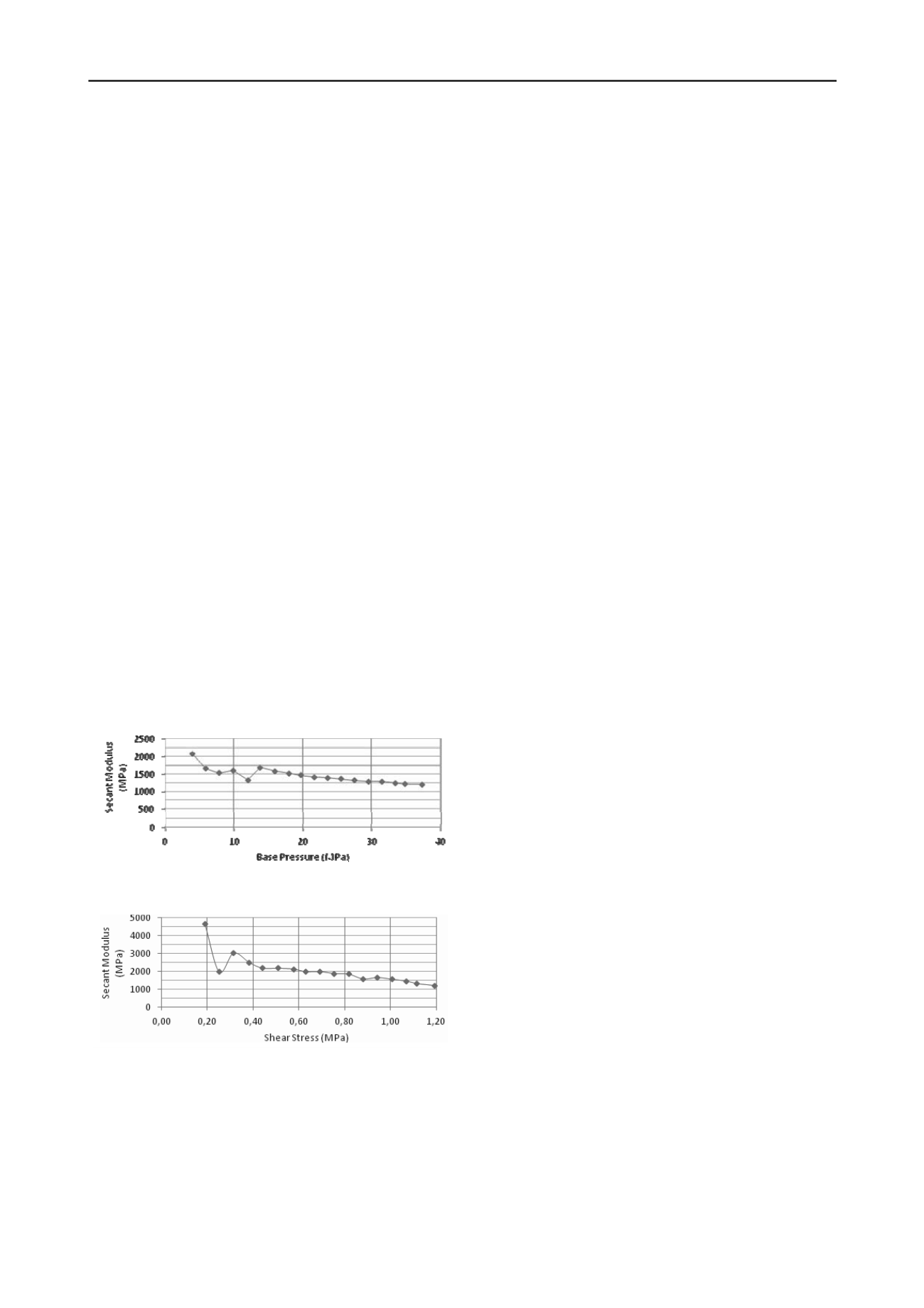
Figure 6. Deduced Secant Modulus of Rock below Pile Base
Figure 7. Deduced Secant Modulus of Rock around Pile Shaft
It can be seen from Figure 6 that there was a rapid drop in
the inferred secant modulus of the rock below the pile base
when a base pressure of 5MPa was reached, and remained at
approximately 1.6GPa to 1.7GPa until a base pressure of
14MPa was reached. Above this pressure, the inferred secant
modulus continued to drop steadily and reached a value of
1.3GPa at a base pressure of 30MPa. The initial drop in secant
modulus at a base pressure of 5MPa to 14MPa could be
attributed to compression of disturbed material or residual
debris at the base of the socket, and the gradual drop of secant
modulus beyond a base pressure of 14MPa is considered to be
representative of the actual rock mass behavior.
From Figure 7, it can be seen that the inferred secant
modulus of the rock socket material was initially very high
(over 5GPa), then dropped rapidly to 2.5GPa at an average shaft
resistance of 0.4MPa, then continued to drop steadily to 1.2GPa
at a mobilized shaft resistance of 1.2MPa. Comparing these
results with the non-linear function to describe the secant
modulus adopted for design as shown in Table 3, it may be
concluded that different initial rock modulus should be applied
to describe the base and shaft response. However, for simplicity
of design, and considering the operating stresses at the
serviceability loads for the piles on this project, it was
concluded that an initial tangent modulus value of 2GPa would
still be appropriate for the Class II Sandstone if the hyperbolic
pile base and shaft factors, R
fb
and R
fs
(see Table 3), were
modified to 0.55 and 0.8 respectively. These values correspond
to secant modulus values of approximately:
Pile Base Response – 1.7GPa and 1.2GPa for the rock
below the pile base, for end bearing pressures of
14MPa and 30MPa respectively, and
Pile Shaft Response – 1.8GPa and 1.2GPa for the rock
around the pile shaft for shaft resistance of 0.4MPa
and 1.2MPa respectively.
However, these changes would only make very small changes
(≤ 3mm) to settlement prediction values at serviceability
loading. Therefore, the original design parameters were
adopted without changes for subsequent designs.
Supported by the O-Cell pile load testing, significant
reduction in pile lengths and cost savings were achieved for this
project as a result of the load-deformation analyses and
performance based design carried out.
4 CONCLUSIONS
Other than very weak to weak rock, socketed pile design is
generally governed by serviceability requirements rather than
ultimate capacity. In such circumstances, economy pile designs
can be achieved if accurate predictions of load-deformation
behavior of the piles are made, rather than adopting recipe style
presumptive values. Pile load testing should be carried out for
such performance based design method.
Two case studies of rock socketed pile design and pile load
testing have been presented in this paper, both of which clearly
illustrated the advantages of this performance based design
approach, with significant cost savings in foundation works.
The use of the O-Cell testing method in Case Study 2
demonstrated the non-linear nature of high strength rock
commonly encountered in the Sydney area of Australia.
5 REFERENCES
Pells P.J.N., Douglas D.J., Rodway, B., Thorne, C.P. and McMahon,
B.R. (1978) Design Loading for Foundations on Shale and
Sandstone in the Sydney Region,
Australian Geomechnics.
Jnl. Vol.
8, 31-39.
Pells P.J.N., Mostyn G., and Walker, B.F. (1998) Foundations on
Sandstone and Shale in the Sydney Region,
Australian
Geomechnics
. Jnl. No. 33 Part 3, 17-29.
Poulos, H.G. (1979) Settlement of Single Piles in Non-homogenous
Soil, Jnl. Geot. Eng. Div., ASCE, Vol. 105, No. GT5, 627-641.
Wong, P.K. and Oliveira, D. (2012) Class A Prediction versus
Performance of O-Cell Pile Load Tests in Sydney Sandstone,
Australian Geomechanics
Jnl,. Vol 47, No. 3, 89-96.
Sethi, P.L., Geng, I. and Wong, P.K. (2012) Construction of Rock
Socketed Piles in Sydney Sandstone to Meet Performance
Requirements,
Australian Geomechan.
Jnl., Vol 47, No. 3, 97-102.
End Bearing Resistance
Maximum mobilised resistance = 59MPa (ultimate end
bearing pressure not reached)
Little or no creep at an end bearing pressure of 38MPa
(this pressure was held for 30 minutes)
Shaft Resistance
Creep started at an average shaft resistance (over 5.5m
length) of 1.06MPa and was significant at 1.3MPa
The shaft response became “plastic” at a movement of
about 30mm, with a corresponding average shaft
resistance of 1.74MPa
The O-Cell test results confirmed the ultim te design values
adopted for design, and as in Case Study 1, demonstrated that
significantly higher serviceability end bearing pressure could be
considered in the design of rock socketed piles in Sydney rock.
If the presumptive end bearing pressure given in Table 2 for
Class I and II Sandstone was adopted, the serviceability end
bearing resistance would have been limited to 12MPa. The O-
Cell test clearly demonstrated that significantly higher
serviceability end bearing could be adopted, provided the base
of the rock socket is adequately cleaned. The pile construction
aspect of this case study to ensure adequate rock socket
roughness and base cleanliness is described in Sethi et al
(2012). However, it should also be stressed that under
serviceability loading, a large proportion of the applied load
may be carried by the pile shaft depending on the length to
diameter ratio of the rock socket. Therefore, the use of
excessively high serviceability end bearing pressure may not be
warranted. A detailed assessment of the rock-socket load-
deformation response is necessary for each specific case.
In the above case study, the non-linear load-deformation
behavior observed from the O-Cell test is of particular interest.
Using the back-analyzed test results, and by close inspection of
the load-deformation behavior of both the shaft and base, it was
possible to deduce the operating secant modulus of the rock
socket material at various mobilized base and shaft resistance as
shown in Figures 6 and 7.
Figure 6. Deduced Secant Modulus of Rock below Pile Base
Figure 7. Deduced Secant Modulus of Rock around Pile Shaft
It can be seen from Figure 6 that there was a rapid drop in
the inferred secant modulus of the rock below the pile base
when a base pressure of 5MPa was reached, and remained at
approximately 1.6GPa to 1.7GPa until a base pressure of
14MPa was reached. Above this pressure, the inferred secant
modulus continued to drop steadily and reached a value of
1.3GPa at a base pressure of 30MPa. The initial drop in secant
modulus at a base pressure of 5MPa to 14MPa could be
attributed to compression of disturbed material or residual
debris at the base of the socket, and the gradual drop of secant
modulus beyond a base pressure of 14MPa is considered to be
representative of the actual rock mass behavior.
From Figure 7, it can be seen that the inferred secant
modulus of the rock socket material was initially very high
(over 5GPa), then dropped rapidly to 2.5GPa at an average shaft
resistance of 0.4MPa, then continued to drop steadily to 1.2GPa
at a mobilized shaft resistance of 1.2MPa. Comparing these
results with the non-linear function to describe the secant
modulus adopted for design as shown in Table 3, it may be
concluded that different initial rock modulus should be applied
to describe the base and shaft response. However, for simplicity
of design, and considering the operating stresses at the
serviceability loads for the piles on this project, it was
concluded that an initial tangent modulus value of 2GPa would
still be appropriate for the Class II Sandstone if the hyperbolic
pile base and shaft factors, R
fb
and R
fs
(see Table 3), were
modified to 0.55 and 0.8 respectively. These values correspond
to secant modulus values of approximately:
Pile Base Response – 1.7GPa and 1.2GPa for the rock
below the pile base, for end bearing pressures of
14MPa and 30MPa respectively, and
Pile Shaft Response – 1.8GPa and 1.2GPa for the rock
around the pile shaft for shaft resistance of 0.4MPa
and 1.2MPa respectively.
However, these changes would only make very small changes
(≤ 3mm) to settlement pr diction values at serviceability
loading. Therefore, the original design parameters were
adopted without changes for subsequent designs.
Supported by the O-Cell pile load testing, significant
reduction in pile lengths and cost savings were achieved for this
project as a result of the load-deformation analyses and
performance based design carried out.
4 CONCLUSIONS
Other than very weak to weak rock, socketed pile design is
generally governed by serviceability requirements rather than
ultimate capacity. In such circumstances, economy pile designs
can be achieved if accurate predictions of load-deformation
behavior of the piles are made, rather than adopting recipe style
presumptive values. Pile load testing should be carried out for
such performance based design method.
Two case studies of rock socketed pile design and pile load
testing have been presented in this paper, both of which clearly
illustrated the advantages of this performance based design
approach, with significant cost savings in foundation works.
The use of the O-Cell testing method in Case Study 2
demonstrated the non-linear nature of high strength rock
commonly encountered in the Sydney area of Australia.
5 REFERENCES
Pells P.J.N., Douglas D.J., Rodway, B., Thorne, C.P. and McMahon,
B.R. (1978) Design Loading for Foundations on Shale and
Sandstone in the Sydney Region,
Australian Geomechnics.
Jnl. Vol.
8, 31-39.
Pells P.J.N., Mostyn G., and Walker, B.F. (1998) Foundations on
Sandstone and Shale in the Sydney Region,
Australian
Geomechnics
. Jnl. No. 33 Part 3, 17-29.
Poulos, H.G. (1979) Settlement of Single Piles in Non-homogenous
Soil, Jnl. Geot. Eng. Div., ASCE, Vol. 105, No. GT5, 627-641.
Wong, P.K. and Oliveira, D. (2012) Class A Prediction versus
Performance of O-Cell Pile Load Tests in Sydney Sandstone,
Australian Geomechanics
Jnl,. ol 47, No. 3, 89-96.
Sethi, P.L., Geng, I. and Wong, P.K. (2012) Construction of Rock
Socketed Piles in Sydney Sandstone to Meet Performance
Requirements,
Australian Geomechan.
Jnl., Vol 47, No. 3, 97-102.
End Bearing R istance
Maximum mobi i ed resi tance = 59MPa (ultimate end
be rin pressure not re ched)
Little or no creep at an end bearing pressure of 38MPa
(this pressure was held for 30 minutes)
Shaft Resistance
Creep started at an average shaft resistance (over 5.5m
length) of 1.06MPa and was significant at 1.3MPa
The shaft respo se became “plastic” at a movement of
about 30mm, with a corr sponding average shaft
resi tance of 1.74MPa
The O-Cell test results confirmed the ultimate de ign values
adopted for design, an as in Case Stu y 1, dem nstrated that
sig ificantly high r serviceability end bearing pressure could be
considered in the design of rock sock ted piles in Sydney rock.
If the presumptive end bearing pressure given in Table 2 for
Class I and II Sandston w s a opte , the serviceability end
bearing resistance would have b en limited to 12MPa. The O-
Cell test clearly demonstrated that significantly higher
serviceability end bearing could be adopted, provided the base
of the r ck socket is adequately cleaned. The pile construction
aspect of this case study to ensure adequate rock socket
roughness and base cl anliness i described in Sethi et al
(2012). However, it should also e stressed that under
serviceability loading, a large proportion of the applied load
may be carried by the pile shaft depending on the length to
diameter r tio of the r ck socket. Therefore, the use of
excessively high serviceability end bearing pressure may not be
warrant d. A detailed assessment of the rock-socket load-
deformation response is necessary for each specific case.
In the above case study, the non-linear load-deformation
behavior observed from the O-Cell test is of particular interest.
Using the back-analyzed test results, and by close inspection of
the load-deformation behavior of both the shaft and base, it was
possible to deduce the operating secant modulus of the rock
socket material at various mobilized base and shaft resistance as
shown in Figures 6 and 7.
Figure 6. Deduced Secant Modulus of Rock below Pile Base
Figure 7. Deduced Secant Modulus of Rock around Pile Shaft
It can e seen from Figure 6 that there was a rapid drop in
the inferred secant modulus of the rock below the pile base
when a base pressure of 5MPa was reached, and remained at
approximately 1.6GPa to 1.7GPa until a base pressure of
14MPa was reached. Above this pressure, the inferred secant
modulus continued to drop steadily and reached a value of
modulus beyond a base pressure of 14MPa is considered to be
representative of the actual rock mass behavior.
From Figure 7, it can be seen that the inferred secant
modulus of the rock socket material was initially very high
(over 5GP ), the dropped rapidly to 2.5GPa at an average shaft
resistance of 0.4MPa, then continued to drop steadil to 1.2GPa
at a mobilized shaft resistance of 1.2MPa. Comparing th se
results with the non-linear function to describe the secant
modulus adopted for design as shown in Table 3, it may be
conclud d that different initial rock modulus sh uld be applied
to describe the base and haft esponse. However, for simplicity
of design, and considering the operating stresses at the
serviceability loads for the piles on this project, it was
concluded that an initial tangent modulus value of 2GPa would
still be appropriate for the Class II Sandston if the hyperbolic
pile base and shaft fac ors, R
fb
a d R
fs
( ee Table 3), were
modified to 0.55 and 0.8 respect ve y. These v lues correspond
to secant modulus values of approximately:
Pile Base Response – 1.7GPa and 1.2GPa for the rock
below the pile base, for end bearing pressures of
14MPa and 30MPa respectively, and
Pile Shaft Response – 1.8GPa and 1.2GPa for the rock
around the pile shaft for shaft resistance of 0.4MPa
and 1.2MPa respectively.
However, these changes would only make v ry small cha ge
(≤ 3mm) to settlement prediction values at se vic ability
loading. Therefore, t e original design paramet rs were
adopt d without changes for subs quent designs.
Supp rted by the O-C ll pile load test n , significant
reduction in pile lengths and cost savings were achieve for this
project as a r sult of the load-deformation analyses and
performanc based design carried out.
4 CONCLUSIONS
Other than very weak to weak rock, socketed pile esign is
generally governed by serviceability requirements rathe than
ultimate capacity. In such circumstances, economy pile esigns
can be achieved if accurate predictions of load-deformation
behavior of the piles are made, rather than adopting recipe style
presumptive values. Pile load testing should be carried out for
such performance based desig method.
Two cas studies of rock s cketed pile d sign a d pile load
testing have been presented in this paper, both of which clearly
illu trated the advantages of this performance based design
approach, with significant cost savings in foundation works.
The use of the O-Cell testing method in Case Study 2
demonstrated the non-linear nature of high strength rock
commonly encountered in the Sydney area of Australia.
5 REFERENCES
Pells P.J.N., D uglas D.J., Rodway, B., Thor e, C.P. and McMahon,
B.R. (1978) Design Loading for Foundations on Shale and
Sandstone in the Sydney Region,
Australian Geomech ics.
Jnl. Vol.
8, 31-39.
Pells P.J.N., Mostyn G., and Walker, B F. (1998) Foundations on
Sandstone and Shale in the Sydney Region,
Australian
Geomechnics
. Jnl. No. 33 Part 3, 17-29.
Poulos, H.G. (1979) Settlement of Single Piles in Non-homogenous
Soil, Jnl. Geot. Eng. Div., ASCE, Vol. 105, No. GT5, 627-641.
Wong, P.K. and Oliveira, D. (2012) Class A Prediction versus
Performance of O-Cell Pile Load Tests in Sydney Sandstone,
Australian Geomechanics
Jnl,. Vol 47, No. 3, 89-96.
Sethi, P.L., Geng, I. and Wong, P.K. (2012) Construction of Rock
End Bearing Resistance
Maximum mobilised resistance = 59MPa (ultimate end
bearing pressure not reached)
Little r no creep at an end bearing pressure of 38MPa
(this pressure was held for 30 minutes)
Sh ft Resistance
Creep started at an average shaft resistance (over 5.5m
length) of 1.06MPa and was significant at 1.3MPa
The shaft response became “plastic” at a movement of
about 30mm, wi h a corr sp di g ver ge shaft
resistance of 1.74MPa
The O-Cell test r sul s confirmed the ultimate esign values
adopted for design, and as in Ca e S udy 1, demonstrat d that
significantly higher serviceability end bearing pressur ould be
consider d in the desi n of ock socket d piles in Sydney rock.
If the presumptive end bearing pressur g ven in Tab 2 for
Class I and II Sandstone was a opted, the s rviceability nd
b aring resistance would have b en limited to 12MPa. The O-
Cell test clearly demon trated that signifi antly higher
serviceability end bearing could be adopte , prov ded the base
of the rock socket is dequately cl a ed. The pile construction
aspect f this case study to ensur adequate rock sock t
roughness and base cleanliness is described in Sethi et al
(2012). However, it should als be stressed th t under
serviceability loading, a large proportion of the applied load
may be c rried by the pile shaft epending on the length to
diameter ratio of the rock socket. Therefore, the use of
excessively high serviceability end bearing pressure may not be
warranted. A etailed assessment of the rock-socket load-
deformation response is necessary for each specific case.
In the above case study, the non-linear load-deformation
behavior observed from the O-Cell test is of particular interest.
Using the back-analyzed test results, and by close inspection of
the load-deformation behavior of both the shaft and base, it was
possible to deduce the operating secant modulus of the rock
socket material at various mobilized base and shaft resistance as
shown in Figures 6 and 7.
Figure 6. Deduced Secant Modulus of Rock below Pile Base
Figure 7. Deduced Secant Mod lus of Rock around Pile Shaft
m dulus eyond base pr ssure of 14MPa is considered to be
repres ntative of the actual rock mass behavior.
From F gure 7, it can be seen that t e inferred secant
m dulus of the rock socket material was initially very high
(over 5GPa), th n dropped rapidly to 2.5GP at an average shaft
resistance of 0.4MPa, then continued to drop t dily to 1.2GPa
at mobilized shaft resistanc of 1.2MPa. Comparing these
results with the no -linear function o describe the secant
modulus adopted for design as shown in Table 3 it may be
concluded that diff rent initial rock modulus should b applied
to des ribe the base and shaft response. However, for simplicity
of design, and considering the operating stresses at the
serviceability loads for the piles on this project, it was
concluded that an initial tangent modulus value of 2GPa would
still be appropriate for the Class II Sandstone if the hyperbolic
pile base and shaft factors, R
fb
and R
fs
(see Table 3), were
modified to 0.55 and 0.8 respectively. These values correspond
to secant modulus values of approximately:
Pile Base Response – 1.7GPa and 1.2GPa for the rock
below the pile base, for end bear ng pressures of
14MPa and 30MPa respectively, and
Pile Shaft Response – 1.8GPa and 1.2GPa for the rock
around the pile shaft for shaft resistance of 0.4MPa
and 1.2MPa respectively.
However, these changes would only make very small change
(≤ 3mm) to settlement pr diction values at serviceability
loading. Therefore, the o igi al design parameters were
ad pted without changes for subsequent designs.
Supported by the O-Cell pile load testing, significant
reduction in pile lengths and cost savings were achieved for this
project as a result of the load-deformation analyses and
performance based design carried out.
4 CONCLUSIONS
Othe than very weak to weak rock, socketed pile design is
generally governed by serviceability requirements rather than
ulti ate capacity. In such circumstances, economy pile designs
can be achi ved if accura e pre ictions of load-deformation
behavior of the piles are made, rather than adopting recipe style
presumptive values. Pile load testing should be carried out for
such performance based design method.
Tw case studie of rock socketed pile design a pile load
testing have b en prese ted in this paper, both of which clearly
illustrated the adv ntages of this performance based design
approach, with significant cost savings in foundation works.
The use of the O-Cell testing method in Case Study 2
demonstrated the non-linear nature of high strength rock
commonly encountered in the Sydney area of Australia.
5 REFERENCES
Pells P.J.N., Douglas D.J., Rodway, B., Thorne, C.P. and McMahon,
B.R. (1978) Design Loading for Foundations on Shale and
End Bearing Resistance
Maximum mobilised resistance = 59MPa (ultimate end
bearing pressur not reached)
Little or no creep at an end bearing pressure of 38MPa
(this pressure was h ld for 30 minutes)
Shaft Resistance
Creep started at an average shaft resistance (over 5.5m
length) of 1.06MPa and was significant at 1.3MPa
The shaft response became “plastic” at a movement of
about 30mm, with a corresponding averag shaft
resistance of 1.74MPa
The O-Cell test results confirmed the ultimate design values
adopted for design, and as in Case Study 1, demonstrated that
significantly higher service bility end bearing pressure could be
considered in the design of rock socketed piles in Sydney rock.
If the presum tive nd bearing pr sure given in Table 2 for
Class I and II Sandstone was a opted, the serviceability end
bearing resistance would have been limited to 12MPa. The O-
Cell test clearly demonstrated that significantly higher
serviceability end bearing could be adopted, provided t e base
of the rock socket is adequately cleaned. The pile construction
aspect of this case study to ensure adequate rock socket
roughness and base cleanliness is described in Sethi et al
(2012). However, it should also be stressed that under
serviceability loading, a large proportion of the applied load
may be carried by the pile shaft depe ding on the length to
diameter ratio of the rock socket. Therefore, the use of
excessively high serviceability end bearing pressure may not be
warranted. A detailed assessment of the rock-socket load-
deformation response is necessary for each specific case.
In the above case study, the non-linear load-deformation
behavior observed from the O-Cell test is of particular interest.
Using the back-analyzed test results, and by close inspection of
the load-deformation behavior of both the shaft and base, it was
possible to deduce the operating secant modulus of the rock
socket material at various mobilized base and shaft resistance as
shown in Figures 6 and 7.
Figure 6. Deduced Secant Modulus of Rock below Pile Base
Figure 7. Deduced Secant Modulus of Rock around Pile Shaft
It can be seen fro Figure 6 that there was a rapid drop in
the inferred secant odulus of the rock below the pile base
when a base pressure of 5MPa was reached, and remained at
approximately 1.6GPa to 1.7GPa until a base pressure of
14MPa was reached. Above this pressure, the inferred secant
modulus continue to drop steadily and reached a value of
1.3GPa at a base pressure of 30MPa. The initial drop in secant
modulus at a base pressure of 5MPa to 14MPa could be
attrib ted to compression of disturbed material or residual
debris at the base of the socket, and the gradual drop of secant
modulus beyond a base pressure of 14MPa is considered to be
representative of the actual rock mass behavior.
From Figure 7, it can be seen that the inferred secant
modulus of the rock socket material was initially very high
( ver 5GPa), then dropped rapidly to 2.5GPa at an average shaft
resistance of 0.4MPa, then continued to drop steadily to 1.2GPa
at a mobilized shaft resistance of 1.2MPa. Comparing these
results with the non-linear function to describe the secant
modulus adopted for design as shown in Table 3, it may be
concluded that different initial rock modulus should be applied
to describe the base and shaft response. However, for sim licity
of design, and considering the operating stresses at the
serviceability loads for the piles on this project, it was
concluded that an initial tangent modulus value of 2GPa would
still be appropriate for the Class II Sandstone if the hyperbolic
pile base and shaft factors, R
fb
and R
fs
(see Table 3), were
modified to 0.55 and 0.8 respectively. These values correspond
t secant modulus values of approximately:
Pile Base Response – 1.7GPa and 1.2GPa for the rock
below the ile base, for end bearing pressures of
14MPa and 30MPa respectively, and
Pile Shaft Response – 1.8GPa and 1.2GPa for the rock
around the pile shaft for shaft resistance of 0.4MPa
and 1.2MPa respectively.
However, these c anges would only make very small changes
(≤ 3mm) to settlement prediction values at serviceability
loading. Therefore, the original design parameters were
adopted without changes for subsequent designs.
Supported by the O-C ll pile load testing, signi icant
reduction in pile lengths and cost savings were achieved for this
project as a result of the load-deformation analyses and
performance based design carried out.
4 CONCLUSIONS
Other than very weak to weak rock, socketed pile design is
generally governed by serviceability requirements rather than
ultimate capacity. In such circumstances, economy pile designs
can be achieved if accurate predictions f load-deformation
behavior of the piles are made, rather than adopting recipe style
presumpt ve values. Pile load testing should be car ied out for
such performa ce based design met od.
Two c se studies of rock socketed pile design and pile load
testing have been presented in this pa er, both of which clearly
illustrated the advantages of this erformance based design
approach, with significant cost savings in foundation works.
The use of the O-Cell testing method in Case Study 2
demonstrated the non-linear nature f high strength rock
commonly encountered in the Sydney area of Australia.
5 REFERENCES
Pells P.J.N., Douglas D.J., Rodway, B., Thorne, C.P. and McMahon,
B.R. (1978) Design Loading for Foundations on Shale and
Sandstone in the Sydney Region,
Australian Geomechnics.
Jnl. Vol.
8, 31-39.
Pells P.J.N., Mostyn G., and Walker, B.F. (1998) Foundations on
Sandstone and Shal in the Sydney Region,
Australian
Geomechnics
. Jnl. N . 33 Part 3, 17-29.
Poulos, H.G. (1979) Settlement of Si gle Piles in Non-homogenous
Soil, Jnl. G ot. Eng. Div., ASCE, Vol. 105, No. GT5, 627-641.
Wong, P.K. and Oliveira, D. (2012) Class A Prediction versus
Performance of O-Cell Pile Load Tests in Sydney Sandstone,
Australian Geomechanics
Jnl,. Vol 47, No. 3, 89-96.
Sethi, P.L., Geng, I. and Wong, P.K. (2012) Construction of Rock
Socketed Piles in Sydney Sandstone to Meet Performance
Requirements,
Australian Geomechan.
Jnl., Vol 47, No. 3, 97-102.


