 
          2899
        
        
          Technical Committee 212 /


            Comité technique 212


          300
        
        
          300
        
        
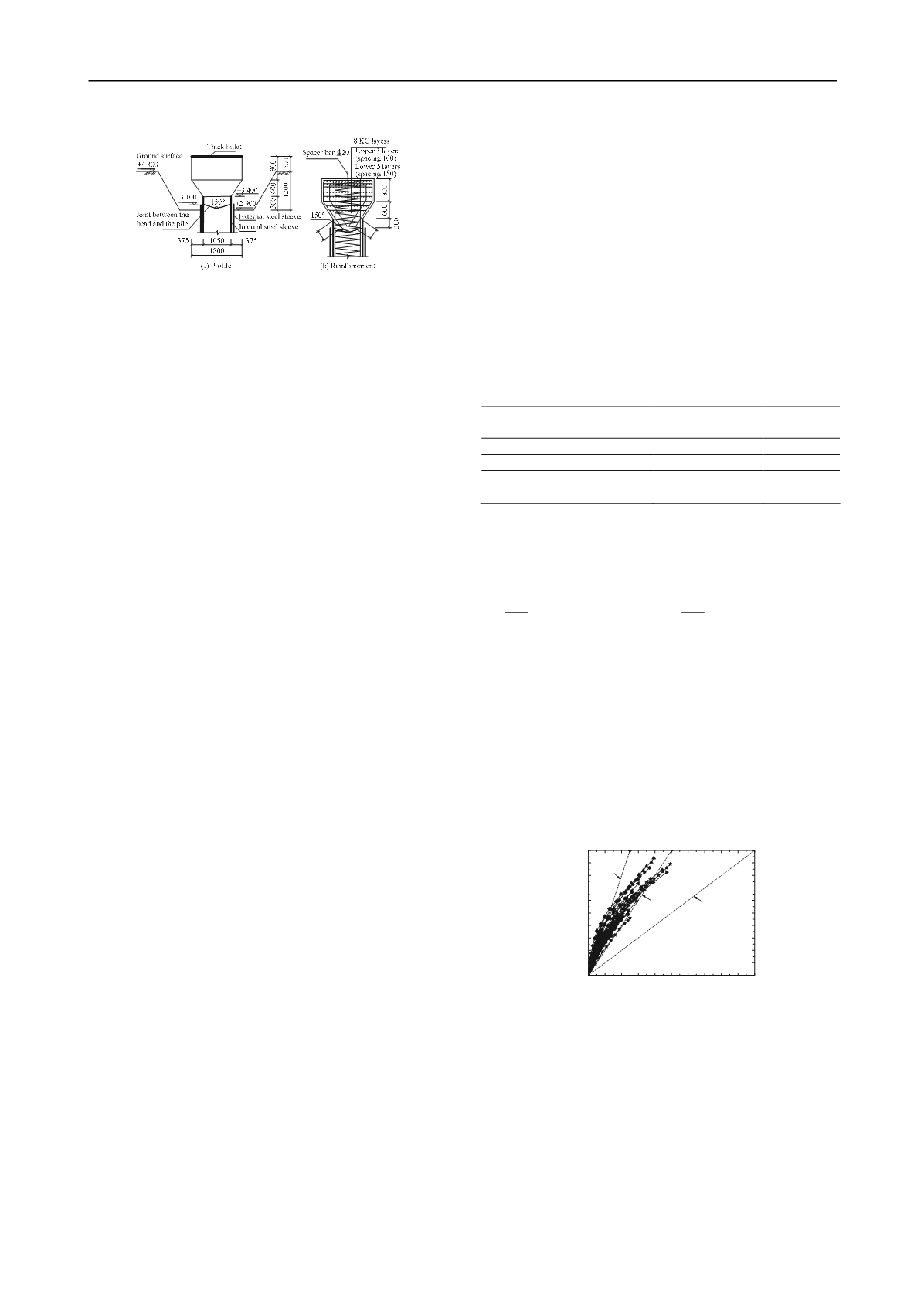
          Figure 2 Design schematic diagrams of the test pile head for the
        
        
          Shanghai Center Tower project


            4.3 CONSTRUCTION AND MEASUREMENT


            REQUIREMENTS


          Practical construction conditions should be simulated in the
        
        
          construction process of the test piles. Artificial drilling fluid and
        
        
          desanding device should be used when the borehole is drilled
        
        
          through the deep sand layers. Vertical deviation of the borehole
        
        
          should be not more than 1/250. Thickness of the sediment at the
        
        
          borehole tip should be less than 50mm after the secondary tip
        
        
          cleaning. If post grouting technique is adopted for the test pile,
        
        
          the grouting construction parameters should be determined. The
        
        
          construction machineries, techniques and parameters are also
        
        
          need to be determined to form a guideline for pile construction.
        
        
          Measurement items of super-long bored pile load test are
        
        
          illustrated as follows: (1) Drilling fluid density, viscosity, sand
        
        
          content and other technical indexes in different depth of the
        
        
          borehole. These parameters should be continuously monitored
        
        
          for not less than 36 hours in the construction process. (2)
        
        
          Concrete quality of the test pile, including pile shaft integrity
        
        
          and concrete strength. (3) Sediment and grouting effect under
        
        
          the test pile tip. (4) Ultimate bearing capacity of the test pile. (5)
        
        
          Pile shaft axial force and pile shaft friction. (6) Pile shaft
        
        
          deformations, including deformations of pile top, pile tip,
        
        
          section at the rock surface, and other pile shaft sections under
        
        
          each load level.
        
        
          5 SINGLE PILE DESIGN


            5.1 PILE ULTIMATE BEARING CAPACITY


          The ultimate bearing capacity of super-long bored pile is
        
        
          determined by filed load test. If the load versus settlement curve
        
        
          of the test pile shows a slowly change in slope, the load
        
        
          corresponding to the pile head settlement of 40mm~60mm or
        
        
          5% of the pile diameter can be used as the ultimate bearing
        
        
          capacity of the pile. For pile foundation under a condition of
        
        
          deep excavation, some factors, such as the soils gravity and pile
        
        
          shaft friction in pit excavation segment and unloading rebound
        
        
          of the soil at the bottom of the pit, should be concerned to
        
        
          determine the ultimate bearing capacity of engineering pile
        
        
          (Wang et al, 2012).
        
        
          Due to the problems of pile shaft mud and pile tip sediment,
        
        
          measured values of the ultimate bearing capacities of the normal
        
        
          super-long bored piles are often lower than the values estimated
        
        
          by empirical methods. Test results of 10 field test piles from 5
        
        
          different sites in Shanghai district were collected by the authors.
        
        
          It illustrates that the ratios of the measured values of the
        
        
          ultimate bearing capacities of the piles to the values estimated
        
        
          by empirical method range from 0.5 to 0.97. The average ratio
        
        
          is 0.69. The pile bearing capacity can be greatly improved by
        
        
          post grouting technique. Measured data of 28 post grouted piles
        
        
          from 9 Shanghai project sites indicate that the average ratio of
        
        
          the measured values of the piles ultimate bearing capacities to
        
        
          the values estimated by empirical method is 1.32. Therefore, the
        
        
          post grouting technique should be adopted for super-long bored
        
        
          piles in deep soft soils.


            5.2 PILE SHAFT STRENGTH AND COMPRESSION


          Due to the application of the post grouting technique, the
        
        
          bearing capacities of the foundation soils around the super-long
        
        
          pile are improved greatly. Therefore, the strength of pile shaft
        
        
          should match well with the bearing capacities of the foundation
        
        
          soils in the design of a single pile. The application of high-
        
        
          strength concrete is helpful to achieve this object. As shown in
        
        
          Table 2, in order to make the piles shaft strength meet the piles
        
        
          bearing capacities requirements, Grade C45 and even Grade
        
        
          C50 concrete were adopted for the foundation piles of several
        
        
          super high-rise buildings in China. Meanwhile, concrete
        
        
          strength can be enhanced by the effect of stirrup constraint.
        
        
          Thus, the spacing of spiral stirrups at the pile top within a scope
        
        
          of about 3


            D


          ~5


            D


          (


            D


          is the pile diameter) should be appropriate
        
        
          reduced to increase the bearing capacity of pile shaft.
        
        
          Table 2 Pile shaft strength of several projects in China
        
        
          Project name
        
        
          Concrete
        
        
          strength grade


            UCS


          (MPa)
        
        
          Shanghai Center Tower
        
        
          C50
        
        
          40.0
        
        
          Shanghai magnolia square
        
        
          C45
        
        
          44.3
        
        
          Tianjin 117 Tower
        
        
          C50
        
        
          59.3
        
        
          Wuhan Center Tower
        
        
          C50
        
        
          54.6
        
        
          Note:


            UCS


          is the average unconfined compressive strength of the
        
        
          concrete drilled from the shaft.
        
        
          Pile shaft compression is a part of the pile top settlement
        
        
          deformation. It is often estimated by the following empirical
        
        
          formula:


          0
        
        
          0
        
        
          s
        
        
          e
        
        
          0
        
        
          0
        
        
          p
        
        
          p
        
        
          1


            L


            z


            Q L


            S


            Q d q z dz dz


            AE


            AE


          (1
        
        
          )
        
        
          Where


            Q


          0
        
        
          is the load applied at pile top;


            L


          is the pile length;


            A


          is
        
        
          the pile section area;


            E


          p
        
        
          is the elastic modulus of the pile shaft;
        
        
          e


          is the pile shaft compression coefficient. For friction pile,
        
        
          e


          =1/2~2/3.
        
        
          According to measured data of nearly 40 super-long bored
        
        
          test piles from 15 sites, diagram of the relationship between the
        
        
          measured values of the pile shaft compression and the
        
        
          calculated value of


            Q


          0


            L


          /


            AE


          p
        
        
          was drawn, as shown in Figure 3.
        
        
          As can be seen from the graph, under the working loads, the pile
        
        
          shaft compression coefficients are less than 1/2. Therefore, the
        
        
          value of
        
        
          e


          for calculating super-long bored pile shaft
        
        
          compression by formula (1) should be not larger than 1/2.
        
        
          0 10 20 30 40 50 60 70 80 90 100
        
        
          0
        
        
          10
        
        
          20
        
        
          30
        
        
          40
        
        
          50
        
        
          60
        
        
          70
        
        
          80
        
        
          90
        
        
          100


          e
        
        
          =1/4


          e
        
        
          =1/2


            Q


          0


            L


          /


            E


          p


            A


          (mm)
        
        
          Measured value of pile shaft compression (mm)


          e
        
        
          =1.0
        
        
          Figure 3 Diagram of the relationship between the measured values of
        
        
          the pile shaft compression and calculated values of


            Q


          0


            L


          /


            AE


          p
        
        
          6 PILE FOUNDATION DESIGN
        
        
          The synergism of the superstructure, foundation soils and pile
        
        
          foundations should be considered in the design calculation of
        
        
          pile foundations for super high-rise buildings. According to this,
        
        
          a practical method for analysis and calculation of the pile
        
        
          foundation is given in this paper. The theoretical framework and
        
        
          procedures of this method are illustrated in Figure 4. The
        
        
          general calculation process is shown in Figure 5.
        
        
          Design calculation of the pile foundation consists of four
        
        
          parts, including foundation settlement calculation, bearing
        
        
          capacity calculation of the grouped piles, bending stress