2890
Proceedings of the 18
th
International Conference on Soil Mechanics and Geotechnical Engineering, Paris 2013
technique to ensure the soundness of solidified improved
columns, especially in relation to the dynamic behavior of piles.
Against this background, a large-scale model experiment
was conducted for the purpose of establishing a new design
verification method for composite ground pile foundations. The
experiment focused on the manifestation of horizontal subgrade
reaction (i.e., the feasibility of the elastic subgrade reaction
design method for piles) in particular when the strength and
depth of solidified improved columns were changed.
3 LARGE-SCALE MODEL EXPERIMENT
3.1
Experiment overview
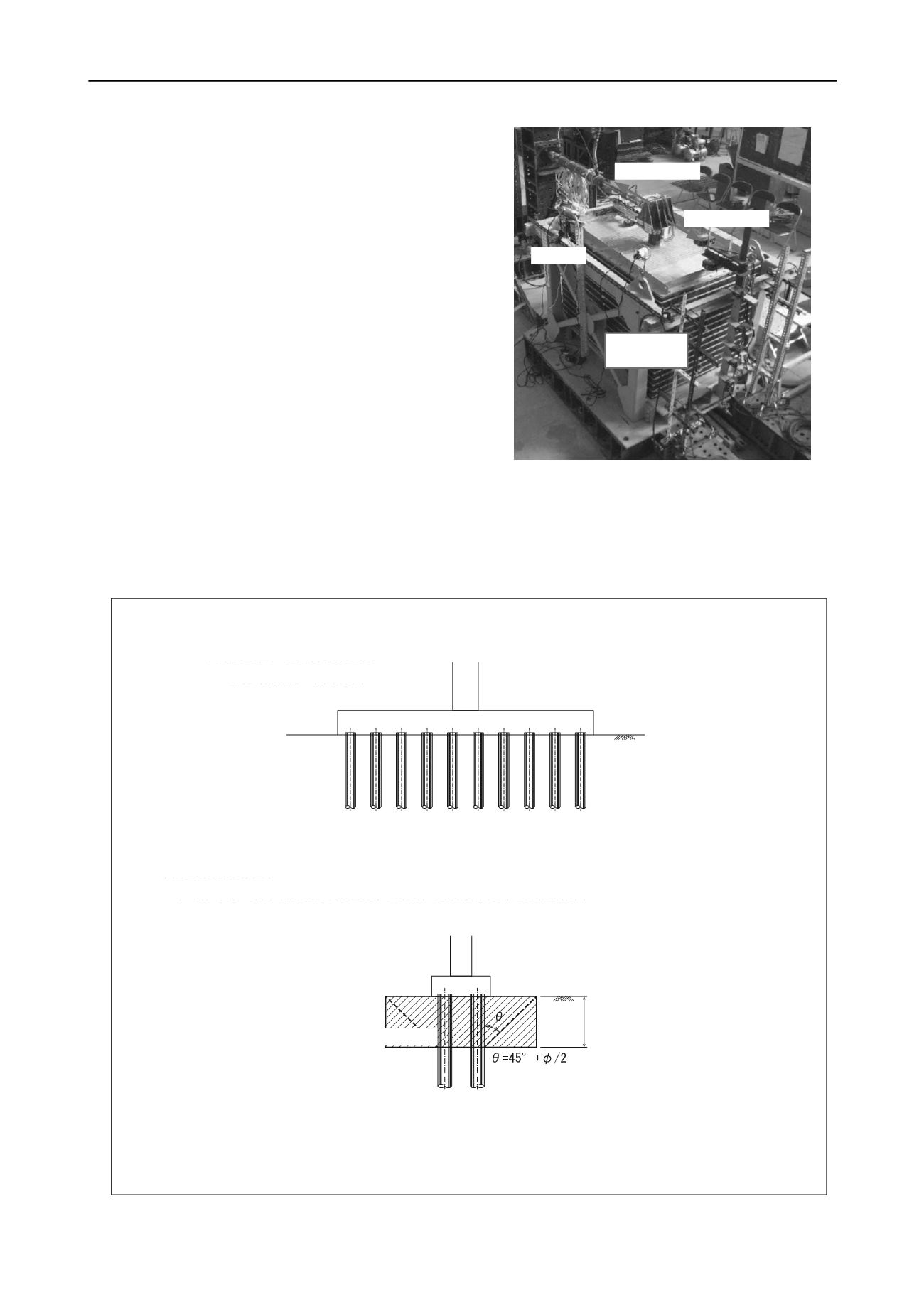
The large-scale model experiment involved static horizontal
cyclic loading tests on piles in composite ground with solidified
improved columns using a laminar shear box (1,200 mm in
width (loading direction) × 800 mm in depth × 1,000 mm in
height) and a 15-tiered shear frame) (Japanese Geotechnical
Society 2010). Photo 1 shows the experimental setup.
The test ground had an upper layer with solidified improved
columns and a lower layer of natural soil to simulate a
composite ground pile foundation. The natural soil was the
sandy type with an
N
value of 10, and was formed with a
compaction water content of w = 5%. The required strength of
the composite ground with solidified improved columns was
achieved using bentonite as the base material and adding early-
strength cement (Public Works Research Center 2004). The test
piles were the point-bearing steel pipe type simulating the actual
scale (pile diameter
D
= 101.6 mm, thickness
t
= 4.2 mm, length
L
= 1,110 mm).
引き側
(
+
)
押し側
(
-
)
In the static horizontal loading experiment, peak-to-peak
alternate loads were applied repeatedly with displacement
controlled. Each loading step was performed three times with
the maximum horizontal displacement of piles at the road
Figure 1. Comparison of the conventional design method for pile foundations in soft ground and composite ground pile foundations
[Conventional design method]
Pile design method for soft ground: Horizontal resistance is insufficient and the foundation is large; the design
method is not feasible.
(Site example) Cast-in-place pile foundation
Pile diameter 1,000 mm / 10 or more rows
Design-related problems: (1) group pile design method, (2) bearing capacity of piles depending on arrangement, (3) bending rigidity of
footing
Problems with other methods: (1) lightweight embankment method: seismic performance; (2) inclined pile foundation: axial force,
bending stress
[Composite ground pile foundation]
Concept: reduction of foundation size and improvement of seismic performance based on the use of piles in
combination with ground improvement
(Site example) Cast-in-place pile foundation
Pile diameter 1,200 mm / 2 or more rows
Solidified improved column
1/
β
or more
Key points of design: (1) composite ground design method, (2) range of 1/
β
or more,
θ
= 45° +
/2), (3) strength:
q
u
= 200 to 500 kN/m
2
Key points of the actual design method:
(1) Normal conditions: elastic subgrade reaction method (sliding/horizontal subgrade reaction verification)
試験杭
せん断土槽
Photo 1. Setup of the large-scale model experiment
Pulling side (+)
Pushing side (-)
Test pile
LAMINAR
SHEAR BOX
(2) During Level-1 earthquake motion: seismic coefficient method (permissible horizontal displacement/cross-sectional force of piles at
the boundary)
(3) During Level-2 earthquake motion: verification of horizontal load bearing capacity during earthquakes (permissible response
ductility), dynamic nonlinear analysis


