2887
Technical Committee 212 /
Comité technique 212
•
The literature that was examined confirms the current limit
value for base resistance (API, 2007; Foray et al., 1998).
•
The limit value for shaft friction seems to be on the low
side. Higher shaft resistances have been measured and also
approved in other, foreign, standards (Foray et al., 1998;
Bustamente et al., 2009).
5 GROUP EFFECTS
Group effects include both the effect of the installation and the
consequences of the higher load in the ground as a result of the
loading of the piles. Both effects are taken into account when
calculating the capacity of tensile piles according to the Dutch
standard. The installation effect of soil-displacement piles with
factor f1 and the effect of the load (in the case of tensile piles,
this is a negative effect) with factor f2.
Factor f1 (NEN 9997-1, 2012) is determined by converting
the volume of the piles into compaction combined with an
empirical relationship that, at a constant vertical stress, links
density to cone resistance qc.
Factor f1 is the ratio of increased to initial qc, and it is
included in the Dutch standard calculation method of the shaft
capacity of a tensile pile. In principle, this factor should also be
included when calculating the compressive shaft capacity of
jacked or driven piles. It is under discussion whether
compaction also occurs to this extent below the level of the pile
base and to what depth, and therefore whether this factor can be
included in the calculation of the pile-base capacity. For this
purpose, the depth to which compaction extends must be
determined, as must the effect of the pile-driving sequencing.
Upward pile movement has been noted during the driving of
piles close to piles that have already been installed; the piles in
place move upward. This could have a negative effect on the
pile-base capacity.
The compaction factor f1 determined as described above
may result in a considerable increase in cone resistance and
consequently of shaft capacity.
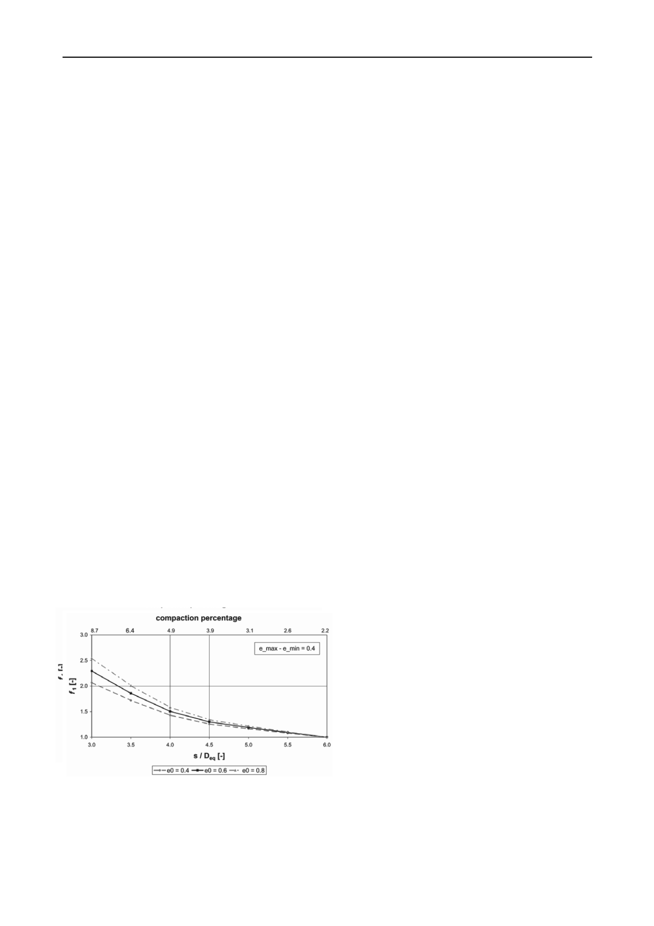
Figure 4 shows, for a symmetric pile field, factor f1 as a
function of the centre-to-centre distance between the piles. For a
symmetrical pile field with a centre-to-centre distance s of, for
example, 4Deq, f1 is approximately 1.5, with a small variation
due to differences in initial density. The compaction percentage
expressed as pile surface to total surface is 5% here, which is
not an extreme value.
Figure 4. Compaction factor f
1
for a pile in a symmetrical pile field
The densification was checked in several projects by
conducting CPTs before and after the installation of the
displacement piles, (van Tol & Everts, 2003). It emerged that
the value f1, as determined in NEN 9997-1 (2012) is a safe
estimate of the installation effect; the compaction found in
practice is usually higher than the predicted value. This is
advisable in a design guideline, particularly because any over-
estimate of the effect will only be noticed during the execution
of the work, with all the associated consequences.
It should be pointed out that the actual installation effect
with soil-displacement (driven) piles is much more complex
than in an approach complying with NEN 9997-1 (2012).
•
In addition to compaction, there is also an increase of
stresses. If the initial density is already high, the increase
of stresses will actually be dominant with respect to
compaction.
•
Not the full volume of the pile is involved in compaction;
soil is also moved upwards.
•
In the immediate vicinity of the pile shaft, in stead of
compaction there is also dilatant behaviour. However, in
the immediate vicinity of the shaft, there may also be
relaxation, which is known as “friction fatigue” as a result
of the up-and-down movement of the shaft during the pile-
driving.
•
Particularly in dense sands, crushing occurs, and the
increase of stresses is therefore limited.
The conclusion with respect to the group effect is that, in
principle, the compaction factor f1 can also be used for driven
piles loaded in compression.
The following, more specific, topics must therefore be
studied in more detail related to the factor f1:
•
Does f1 also apply to the pile-base capacity and, if so,
down to what depth below the pile base does compaction
occur and what role is played by pile-driving sequencing?
•
Does f1 also apply to small, highly compact, groups of
piles?
•
Is the value of f1 affected by the properties of the sand
such as particle-size distribution, form, strength and the silt
concentration?
6 WIND LOAD AND NEGATIVE SKIN FRICTION
In the current design approach, wind load is transferred to the
load-bearing sand layer. In the western part of the Netherlands,
where the Pleistocene sand is covered by a thick layer of
Holocene clay and peat layers, piles are subjected to negative
skin friction. The loads generated by negative skin friction can
be very considerable, rising to more than 30% of the total pile
load. Wind load is another major, temporary, component of the
total load, particularly in the case of high-rise buildings. In the
case of piles in which negative skin friction is fully developed,
wind load will initially result in the pile being pushed
downwards, decreasing the amount of negative skin friction. A
number of calculations have been conducted for this
phenomenon using an interaction model. Figure 5 shows a
calculated result for the fluctuation of forces in a pile shaft, first
when the pile is subjected only to a permanent load of 1000 kN
and 550 kN negative skin friction. Then there is an additional
temporary wind load of 600 kN. Negative skin friction drops
from 550 to 300kN. In other words, (550-300) / 600 =
approximately 40% of the wind load is transferred to the upper
Holocene layers.
This factor can therefore certainly not be neglected and, in
this case, represents a concealed safety factor in current design
practice.
However, it should be kept in mind that wind load makes a
significant contribution only when the height of the building
exceeds 40 m. The contribution in the total load in that case is
approximately 10% (so much smaller than in the example of
figure 5). This means that the wind load transferred to the upper
layers is therefore only a concealed safety factor in specific
conditions of high buildings.
•
The literature that was examined confirms the current limit
value for base resistance (API, 2007; Foray et al., 1998).
•
The limit value for shaft friction seems to be on the low
side. Higher shaft resistances have been measured and also
approved in other, foreign, standards (Foray et al., 1998;
Bustamente et al., 2009).
5 GROUP EFFECTS
Group effects include both the effect of the installation and the
consequences of the higher load in the ground as a result of the
loading of the piles. Both effects are taken into account when
calculating the capacity of tensile piles according to the Dutch
standard. The installation effect of soil-displacement piles with
factor f1 and the effect of the load (in the case of tensile piles,
this is a negative effect) with factor f2.
Factor f1 (NEN 9997-1, 2012) is determined by converting
the volume of the piles into compaction combined with an
empirical relationship that, at a constant vertical stress, links
density to cone resistance qc.
Factor f1 is the ratio of increased to initial qc, and it is
included in the Dutch standard calculation method of the shaft
capacity of a tensile pile. In principle, this factor should also be
included when calculating the compressive shaft capacity of
jacked or driven piles. It is under discussion whether
compaction also occurs to this extent below the level of the pile
base and to what depth, and therefore whether this factor can be
included in the calculation of the pile-base capacity. For this
purpose, the depth to which compaction extends must be
determined, as must the effect of the pile-driving sequencing.
Upward pile movement has been noted during the driving of
piles close to piles that have already been installed; the piles in
place move upward. This could have a negative effect on the
pile-base capacity.
The compaction factor f1 determined as described above
may result in a considerable increase in cone resistance and
consequently of shaft capacity.
Figure 4 shows, for a symmetric pile field, factor f1 as a
function of the centre-to-centre distance between the piles. For a
symmetrical pile field with a centre-to-centre distance s of, for
example, 4Deq, f1 is approximately 1.5, with a small variation
due to differences in initial density. The compaction percentage
expressed as pile surface to total surface is 5% here, which is
not an extreme value.
Figure 4. Compaction factor f
1
for a pile in a symmetrical pile field
The densification was checked in several projects by
conducting CPTs before and after the installation of the
displacement piles, (van Tol & Everts, 2003). It emerged that
the value f1, as determined in NEN 9997-1 (2012) is a safe
estimate of the installation effect; the compaction found in
practice is usually higher than the predicted value. This is
advisable in a design guideline, particularly because any over-
estimate of the effect will only be noticed during the execution
of the work, with all the associated consequences.
It should be pointed out that the actual installation effect
with soil-displacement (driven) piles is much more complex
than in an approach complying with NEN 9997-1 (2012).
•
In addition to compaction, there is also an increase of
stresses. If the initial density is already high, the increase
of stresses will actually be dominant with respect to
compaction.
•
Not the full volume of the pile is involved in compaction;
soil is also moved upwards.
•
In the immediate vicinity of the pile shaft, in stead of
compaction there is also dilatant behaviour. However, in
the immediate vicinity of the shaft, there may also be
relaxation, which is known as “friction fatigue” as a result
of the up-and-down movement of the shaft during the pile-
driving.
•
Particularly in dense sands, crushing occurs, and the
increase of stresses is therefore limited.
The conclusion with respect to the group effect is that, in
principle, the compaction factor f1 can also be used for driven
piles loaded in co pression.
The following, more specific, topics must therefore be
studied in more detail related to the factor f1:
•
Does f1 also apply to the pile-base capacity and, if so,
down to what depth below the pile base does compaction
occur and what role is played by pile-driving sequencing?
•
Does f1 also apply to small, highly compact, groups of
piles?
•
Is the value of f1 affected by the properties of the sand
such as particle-size distribution, form, strength and the silt
concentration?
6 WIND LOAD AND NEGATIVE SKIN FRICTION
In the current design approach, wind load is transferred to the
load-bearing sand layer. In the western part of the Netherlands,
where the Pleistocene sand is covered by a thick layer of
Holocene clay and peat layers, piles are subjected to negative
skin friction. The loads generated by negative skin friction can
be very considerable, rising to more than 30% of the total pile
load. Wind load is another major, temporary, component of the
total load, particularly in the case of high-rise buildings. In the
case of piles in which negative skin friction is fully developed,
ind load will initially result in the pile being pushed
downwards, decreasing the amount of negative skin friction. A
number of calculations have been conducted for this
phenomenon using an interaction model. Figure 5 shows a
calculated result for the fluctuation of forces in a pile shaft, first
when the pile is subjected only to a permanent load of 1000 kN
and 550 kN negative skin friction. Then there is an additional
temporary wind load of 600 kN. Negative skin friction drops
from 550 to 300kN. In other words, (550-300) / 600 =
approximately 40% of the wind load is transferred to the upper
Holocene layers.
This factor can therefore certainly not be neglected and, in
this case, represents a concealed safety factor in current design
practice.
However, it should be kept in mind that wind load makes a
significant contribution only when the height of the building
exceeds 40 m. The contribution in the total load in that case is
approximately 10% (so much smaller than in the example of
figure 5). This means that the wind load transferred to the upper
layers is therefore only a concealed safety factor in specific
conditions of high buildings.
Bustamente et al., 2009).
5 GROUP EFFECTS
Group effects include both the effect of the installation and the
consequences of the higher load in the ground as a result of the
loading of the piles. Both effects are taken into account when
calculating the capacity of tensile piles according to the Dutch
standard. The installation effect of soil-displacement piles with
factor f1 and the effect of the load (in the case of tensile piles,
this is a negative effect) with factor f2.
Factor f1 (NEN 9997-1, 2012) is determined by converting
the volume of the piles into compaction combined with an
empirical relationship that, at a constant vertical stress, links
density to cone resistance qc.
Factor f1 is the ratio of increased to initial qc, and it is
included in the Dutch standard calculation method of the shaft
capacity of a tensile pile. In principle, this factor should also be
included when calculating the compressive shaft capacity of
jacked or driven piles. It is under discussion whether
compaction also occurs to this extent below the level of the pile
base and to what depth, and therefore whether this factor can be
included in the calculation of the pile-base capacity. For this
purpose, the depth to which compaction extends must be
determined, as must the effect of the pile-driving sequencing.
Upward pile movement has been noted during the driving of
piles close to piles that have already been installed; the piles in
place move upward. This could have a negative effect on the
pile-base capacity.
The compaction factor f1 determined as described above
may result in a considerable increase in cone resistance and
consequently of shaft capacity.
Figure 4 shows, for a symmetric pile field, factor f1 as a
function of the centre-to-centre distance between the piles. For a
symmetrical pile field with a centre-to-centre distance s of, for
example, 4Deq, f1 is approximately 1.5, with a small variation
due to differences in initial density. The compaction percentage
expressed as pile surface to total surface is 5% here, which is
not an extreme value.
Figure 4. Compaction factor f
1
for a pile in a symmetrical pile field
The densification was checked in several projects by
conducting CPTs before and after the installation of the
displacement piles, (van Tol & Everts, 2003). It emerged that
the value f1, as determined in NEN 9997-1 (2012) is a safe
estimate of the installation effect; the compaction found in
practice is usually higher than the predicted value. This is
than in an approach complying with NEN 9997-1 (2012).
•
In addition to compaction, there is also an increase of
stresses. If the initial density is already high, the increase
of s resses will actually be dominant with respect to
compaction.
•
Not the full volume of the pile is involved in compaction;
soil is also moved upwards.
•
In the immediate vicinity of the pile shaft, in stead of
compaction there is also dilatant behaviour. However, in
the immediate vicinity of the shaft, there may also be
relaxation, which is known as “friction fatigue” as a result
of the up-and-down m vement f the shaft during th pile-
driving.
•
Particularly in dense sands, crushing occurs, nd he
increase of stresses is therefore limited.
The conclusion with respect to the group effect is that, in
principle, the compaction factor f1 can also be used for driven
piles loaded in compression.
The following, more specific, topics must therefore be
studied in more detail related to the factor f1:
D es f1 also apply to the pile-ba e capacity and, if so,
d wn to what depth below the pile base does compaction
occur and what role is played by pile-driving equencing?
•
D es f1 also apply to mall, highly compact, groups of
pil s?
•
Is the value of f1 affected by the properties of the s nd
suc as particle-size distribution, form, strength and the silt
concentration?
6 WIND LOAD AND NEGATIVE SKIN FRICTION
In the current desig approach, wind load is transferred to the
load-bearing sand layer. In the western part of th Netherlands,
where the Pleistocene sand is covered by a thick layer of
Holocene clay and peat layers, piles are subjected to negative
skin frictio . The loads g nerated by negative skin friction can
be very c n iderable, rising to mor than 30% of the total pile
load. Wind load is another maj r, em orary, component of the
total load, particularly in the case of high-rise buildings. I the
case of pil in which negative skin friction is fully developed,
wind load will initially result in the pile being pushed
downwards, decreasing the amount of negative skin frictio . A
number of calculations have bee conducted for t is
phenomenon using an interaction model. Figure 5 shows a
calculated result for the fluctuation of forces in a pile shaft, first
when the pile is subjected only to a permanent load of 1000 kN
and 550 kN negative skin friction. Then there is an additional
temporary wind load of 600 kN. Negative skin friction drops
from 550 to 300kN. In other words, (550-300) / 600 =
approximately 40% of the wind load is transferred to the upper
Holocene layers.
This factor can therefore certainly not be neglected and, in
this case, represents a concealed safety factor in current design
practice.
However, it should be kept in mind that wind load makes a
significant contribution only when the height of the building
exceeds 40 m. The contribution in the total load in that case is
approximately 10% (so much smaller than in the example of
figure 5). This means that the wind load transferred to the upper
layers is therefore only a concealed safety factor in specific
conditions of high buildings.


