2891
Technical Committee 212 /
Comité technique 212
surface
y
(1) 0.5 mm, (2) 1.0 mm, (3) 2.5 mm and (4) 5.0 mm,
which was set at the time of design to simulate normal and
earthquake conditions.
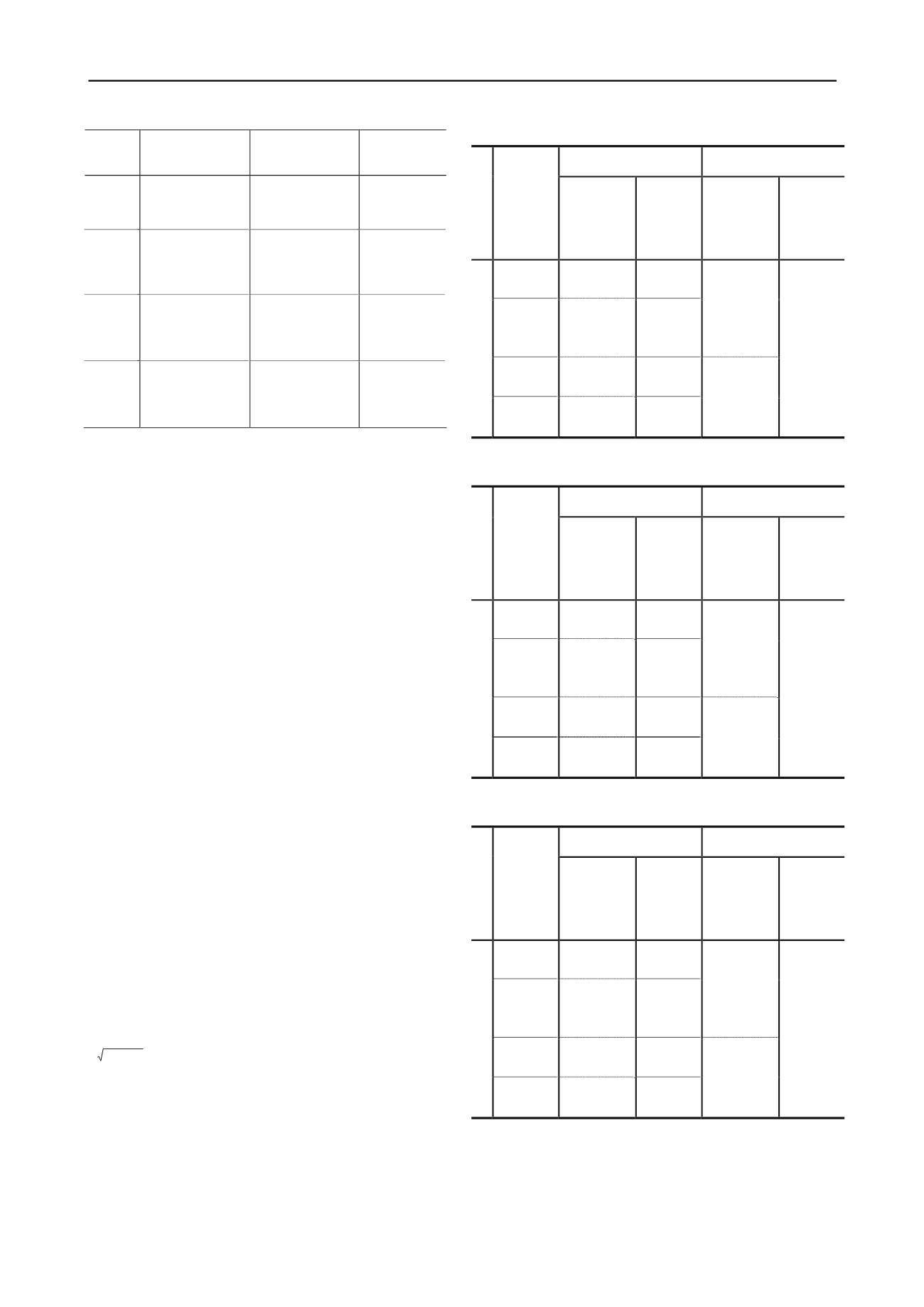
Table 1. Experiment cases
Experiment
case
Ground condition
Unconfined compressive
strength
q
u
(kN/m
2
)
The large-scale part of the model experiment was conducted
for the four cases listed in Table 1. Case 1 involved natural
ground with no improvement and an N value of 10 for the entire
layer. Case 2 involved two-layered ground where the
unconfined compressive strength of the solidified improved
columns in the upper layer qu was close to the standard value of
q
u
= 200 kN/m
2
(223 kN/m
2
in actual strength) and the
improvement depth was 1/
β
= 50 cm in accordance with the
basic design method for composite ground pile foundations.
Case 3 involved two-layered ground where the improvement
depth of solidified improved columns in the upper layer was 1/
β
= 50 cm and the unconfined compressive strength
q
u
was
around 1,000 kN/m
2
(1,440 kN/m
2
in actual strength), which
was about five times as large as that of Case 2 (ratio in actual
strength: 1,440 kN/m
2
/ 223 kN/m
2
≈ 6.5 times). Case 4
involved two-layered ground where the unconfined compressive
strength of solidified improved columns in the upper layer was
similar to that of Case 2 (205 kN/m
2
in actual strength) and the
improvement depth was half (1/2
β
= 25 cm).
3.2
Results of horizontal subgrade reaction experiment
Tables 2 to 4 summarize the experimental results regarding the
horizontal subgrade reaction in Cases 2 to 4 as obtained from
the large-scale model experiment. The actual modulus of
subgrade reaction
k
in the horizontal direction in the table was
found via back-calculation from the basic equation of the elastic
subgrade reaction method for finite piles (Eq. (1)) based on the
H-y relationship at each displacement as found from the static
horizontal cyclic loading experiment (Japan Road Association
2002).
y
= (
C
1
+
C
2
) / (2
EIβ
3
)
(1)
Here,
C
1
and
C
2
are the integral constants of the pile head
fixation condition,
β
is the characteristic value of piles (m
-1
)
β
=
4
,
D
is the pile diameter (m) and
EI
is the pile bending
rigidity (kN/m
2
). The measured horizontal subgrade reaction
P
H
was set as the product of the modulus of subgrade reaction in
the horizontal direction
k
and the displacement of piles at the
ground surface (maximum displacement).
4/) (
EI
kD
The design modulus of subgrade reaction in the horizontal
direction
k’
was calculated as the modulus of deformation
E
for
the solidified improved columns. The design horizontal
subgrade reaction
P
HU
was assumed to be the upper-limit value
of the horizontal subgrade reaction, which is the passive earth
pressure strength of composite ground with solidified improved
columns as calculated using Eq. (2) (Japan Road Association
2002).
p u S
HU
aqa P
(2)
Here,
α
S
is the correction factor for composite ground in
which solidified improved columns are used, and was set as 1.5
as in the calculation for cohesive soil ground in consideration of
related physical properties.
The experiment results were examined as described here.
First, the modulus of the subgrade reaction in the horizontal
Remarks
CASE-1
Entire layer: natural
ground 1.00 m
-
No improved
ground (natural
ground)
CASE-2
Upper layer: solidified
improved columns 0.50
m (= 1/β); lower layer:
natural ground 0.50 m
200
(actual strength: 223)
Standard
strength
CASE-3
Upper layer: solidified
improved columns 0.50
m (= 1/β); lower layer:
natural ground 0.50 m
1000
(actual strength: 1,440)
Varied
improvement
strength
CASE-4
Upper layer: solidified
improved columns 0.25
m (= 1/2β); lower layer:
natural ground 0.75 m
200
(actual strength: 205)
Varied
improvement
depth
Table 2. Modulus of subgrade reaction in the horizontal direction
k
and
horizontal subgrade reaction
P
H
in Case 2
Experiment value
Design value
Experiment case
Pile displacement at
the ground surface
(ratio to pile diameter)
Modulus of
subgrade reaction
in the horizontal
direction
k
(kN/m
3
)
Horizontal
subgrade
reaction
P
H
(kN/m
2
)
Modulus of
subgrade reaction
in the horizontal
direction
Horizontal
subgrade
reaction
k’
(kN/m
3
)
P
HU
(kN/m
2
)
0.5 [0.5%]
383,466
191.7
1.0 [1.0%]
233,577
233.6
Composite
ground with
solidified
improved
columns
395,642
2.5 [2.5%]
121,290
303.2
CASE-2
5.0 [5.0%]
73,880
369.4
Natural
ground with an
N
value of
around 10
Upper-limit
value for
solidified
improved
columns
110,165
334.5
Table 3. Modulus of subgrade reaction in the horizontal direction
k
and
horizontal subgrade reaction
P
H
in Case 3
Experiment value
Design value
Experiment case
Pile displacement at
the ground surface
(ratio to pile diameter)
Modulus of
subgrade reaction
in the horizontal
direction
k
(kN/m
3
)
Horizontal
subgrade
reaction
P
H
(kN/m
2
)
Modulus of
subgrade reaction
in the horizontal
direction
Horizontal
subgrade
reaction
k’
(kN/m
3
)
P
HU
(kN/m
2
)
0.5 [0.5%] 2,150,363
1,075.2
1.0 [1.0%] 1,056,491
1,056.5
Composite
ground with
solidified
improved
columns
3,098,529
2.5 [2.5%]
412,912
1,032.3
CASE-3
5.0 [5.0%]
202,867
1,014.3
Natural
ground with an
N
value of
around 10
Upper-limit
value for
solidified
improved
columns
110,165
2,160.0
Table 4. Modulus of subgrade reaction in the horizontal direction
k
and
horizontal subgrade reaction
P
H
in Case 4
Experiment value
Design value
Experiment case
Pile displacement at
the ground surface
(ratio to pile diameter)
Modulus of
subgrade reaction
in the horizontal
direction
k
(kN/m
3
)
Horizontal
subgrade
reaction
P
H
(kN/m
2
)
Modulus of
subgrade reaction
in the horizontal
direction
Horizontal
subgrade
reaction
k’
(kN/m
3
)
P
HU
(kN/m
2
)
0.5 [0.5%]
295,440
147.7
1.0 [1.0%]
188,945
188.9
Composite
ground with
solidified
improved
columns
240,555
2.5 [2.5%]
104,641
261.6
CASE-3
5.0 [5.0%]
66,922
334.6
Natural
ground with an
N
value of
around 10
Upper-limit
value for
solidified
improved
columns
307.5
110,165


