2896
Proceedings of the 18
th
International Conference on Soil Mechanics and Geotechnical Engineering, Paris 2013
This difference is explained by the fact that during the
tapered anchor installation, the upper helices pass through intact
soil, differently of the upper helices of cylindrical anchor.
However, during the loading of the both anchors, the both
surfaces of soil mobilized above the plates are disturbed by the
installation of the helices.
3 CONCLUSIONS
Two different types of experimental programs were carried on
helical anchors to verify the effect of the helices configuration
on the anchor uplift capacity. Based on the results of these tests,
the most important conclusions are:
The efficiency of the second helix of helical anchors in sand
decrease with the increase of the relative density and the
helix diameter.
2.2.1 Results of field tests
All anchors of this field investigation were installed with the
anchor tip at a depth of 10 meters as illustrated in Figure 7.
After installation, tension load tests were carried out on the
anchors shown in Figure 6. More complete details of this
investigation are available in Santos (2012).
The uplift capacity of a triple-helix anchor with tapered
helices is slightly superior then the one of cylindrical
helices, with same average plate diameter in a tropical soil.
4 ACKNOWLEDGEMENTS
The ultimate capacity (Q
u
) of all tests was taken as the load
producing a relative displacement of 10% of the helix average
diameter. Table 3 presents the results of ultimate capacity (Q
u
)
of the tested anchors, and also the fractions of uplift capacity
related the upper plates. Considering the homogeneity of this
site, the fractions of uplift bearing capacity of the second plate
of the multi-helix anchors (F
Qh2
) were calculated by the
difference between the ultimate capacity of anchors with two
helices and of one helix (same bottom helix diameter). The
fractions of uplift capacity due to the third plate (F
Qh3
) of three-
helix anchors were calculated by using the same procedure.
The authors wish to thank FAPESP (Fundação de Amparo à
Pesquisa do Estado de São Paulo) project n
o
2010/19039-6, and
the
international
Cooperation
USP/Cofecub
project
n
o
2012.1.678.1.9.
5 REFERENCES
Clemence, S.P., Crouch, L.K., and Stephenson, R.W. 1994. Prediction
of uplift capacity for helical anchors in sand. In Proceedings of the
2nd Geotechnical Engineering Conference, Egypt. Vol. I: 332–343.
The comparison between the double-helix anchor A2
(cylindrical) and B2 (tapered) shows that the contribution of the
second helix to the total capacity is better for tapered
configuration. The second helix of the anchor B2 is larger than
the bottom helix, and installed in a less disturbed soil layer
compared to the second helix of the cylindrical anchor A2.
Kulhawy, F.H. 1985. Uplift behaviour of shallow soil anchors — an
overview. In Uplift Behaviour of Anchor Foundations in Soil.
ASCE: 1–25.
Lutenegger, A.J. 2009. Cylindrical Shear or Plate Bearing? – Uplift
Behavior of Multi-Helix Screw Anchors in Clay. Contemporary
Issues in Deep Foundations, ASCE: 456-463.
Table 3. Contribution of the upper plates to the total anchor uplift
capacity.
Lutenneger, A.J. 2011. Behavior of multi-helix screw anchors in sand.
In Proceedings of the 14th Pan-American Conference on Soil
Mechanics and Geotechnical Engineering
, Toronto, Ont. [CD
ROM].
Mitsch, M.P., and Clemence, S.P. 1985. Uplift capacity of helix anchors
in sand. In Uplift Behaviour of Anchor Foundations in Soil, ASCE:
26-47.
Anchor
Helices
diameters
(mm)
Q
u
(kN)
F +
Qh1
Q
s
fraction
(%)
F
Qh2
(%)
F
Qh3
(%)
A1
200
14,5
100.0
A2
200/200
25
58.0
42.0
A3 200/200/200
36
40.3
29.2
30.6
B1
150
13,5
100.0
B2
150/200
31
43.5
56.5
B3 150/200/250
39
34.6
44.9
20.5
C2
200/250
48
30.2
69.8
C3 200/250/300
57
25.4
58.8
15.8
Mooney, J.S., Adamczak, S.J, and Clemence, S.P. 1985. Uplift Capacity
of Helix Anchors in Clay and Silt. Uplift Behaviour of Anchor
Foundations in Soil, ASCE: 48-72.
Sakr, M. 2009. Performance of helical piles in oil sand.
Canadian
Geotechnical Journal
46: 1046–1061.
Santos, T.C. 2012. The effect of helices configuration on the uplift
capacity of helical piles in a tropical soil. Dissertation (master's
degree) – Escola de Engenharia de São Carlos, Universidade de São
Paulo, São Carlos.
However, from the comparison between the third helix
contribution to the total capacity (F
Qh3
) of three-helix anchors
A3, B3, and C3, it could be observed that the efficiency of the
third helix decreases with the third plate diameter, even for the
tapered anchors. A similar trend was observed in the centrifuge
tests presented in this paper. However, further investigation is
needed to confirm this behaviour.
Terzaghi, K. 1943.
Theoretical soil mechanics
. John Wiley & Sons,
New York.
Tsuha, C.H.C., Aoki, N., Rault, G., Thorel, L., and Garnier, J. 2007.
Physical modeling of helical pile anchors.
International Journal of
Physical Modelling in Geotechnics
7(4): 1–12.
Tsuha, C.H.C., Aoki, N., Rault, G., Thorel, L., and Garnier, J. 2012.
Evaluation of the efficiencies of helical anchor plates in sand by
centrifuge model tests.
Canadian Geotechnical Journal
49: 1102–
1114.
2.2.2 Cylindrical and tapered helices
The results of the final installation torque and the uplift capacity
of helical anchors with same average plate diameter (A3 and
B3) were compared. From this comparison it was found that the
gain in uplift capacity for the tapered anchor is about 8%.
However, to install the tapered model, it was necessary to apply
a torque 20% larger than the needed to install the cylindrical
model.
However, from the comparison between the third helix
contribution to the total capacity (F
Qh3
) of three-helix anchors
A3, B3, and C3, it could be observed that the efficiency of the
third helix decreases with the third plate diameter, even for the
tapered anchors. A similar trend was observed in the centrifuge
tests presented in this paper. However, further investigation is
needed to confirm this behaviour.
Tsuha, C.
Physic
Physic
Tsuha, C.
Evalua
centrif
1114.
2.2.2 Cylindrical and tapered helices
The results of the final installation torque and the uplift capacity
of helical anchors with same average plate diameter (A3 and
B3) were compared. From this comparison it was found that the
gain in uplift capacity for the tapered anchor is about 8%.
However, to install the tapered model, it was necessary to apply
a torque 20% larger than the needed to install the cylindrical
model.
This difference is explained by the fact that during the
tapered anchor installation, the upper helices pass through intact
soil, differently of the upper helices of cylindrical anchor.
However, during the loading of the both anchors, the both
surfaces of soil mobilized above the plates are disturbed by the
installation of the helices.
3 CONCLUSIONS
Two different types of experimental programs were carried on
helical anchors to verify the effect of the helices configuration
on the anchor uplift capacity. Based on the results of these tests,
the most important conclusions are:
The efficiency of the second helix of helical anchors in sand
decrease with the increase of the relative density and the
helix diameter.
2.2.1 Results of field tests
All anchors of this field investigation were installed with the
anchor tip at a depth of 10 meters as illustrated in Figure 7.
After installation, tension load tests were carried out on the
anchors shown in Figure 6. More complete details of this
investigation are available in Santos (2012).
The uplift capacity of a triple-helix anchor with tapered
helices is slightly superior then the one of cylindrical
helices, with same average plate diameter in a tropical soil.
4 ACKNOWLEDGEMENTS
The ultimate capacity (Q
u
) of all tests was taken as the load
producing a relative displacement of 10% of the helix average
diameter. Table 3 presents the results of ultimate capacity (Q
u
)
of the tested anchors, and also the fractions of uplift capacity
related the upper plates. Considering the homogeneity of this
site, the fractions of uplift bearing capacity of the second plate
of the multi-helix anchors (F
Qh2
) were calculated by the
difference between the ultimate capacity of anchors with two
helices and of one helix (same bottom helix diameter). The
fractions of uplift capacity due to the third plate (F
Qh3
) of three-
helix anchors were calculated by using the same procedure.
The authors wish to thank FAPESP (Fundação de Amparo à
Pesquisa do Estado de São Paulo) project n
o
2010/19039-6, and
the
international
Cooperation
USP/Cofecub
project
n
o
2012.1.678.1.9.
5 REFERENCES
Clemence, S.P., Crouch, L.K., and Stephenson, R.W. 1994. Prediction
of uplift capacity for helical anchors in sand. In Proceedings of the
2nd Geotechnical Engineering Conference, Egypt. Vol. I: 332–343.
The comparison between the double-helix anchor A2
(cylindrical) and B2 (tapered) shows that the contribution of the
second helix to the total capacity is better for tapered
configuration. The second helix of the anchor B2 is larger than
the bottom helix, and installed in a less disturbed soil layer
compared to the second helix of the cylindrical anchor A2.
Kulhawy, F.H. 1985. Uplift behaviour of shallow soil anchors — an
overview. In Uplift Behaviour of Anchor Foundations in Soil.
ASCE: 1–25.
Lutenegger, A.J. 2009. Cylindrical Shear or Plate Bearing? – Uplift
Behavior of Multi-Helix Screw Anchors in Clay. Contemporary
Issues in Deep Foundations, ASCE: 456-463.
Table 3. Contribution of the upper plates to the total anchor uplift
capacity.
Lutenneger, A.J. 2011. Behavior of multi- elix screw anchors in sand.
In Proceedings of the 14th Pan-American Conference on Soil
Mechanics an Geotechnical Engineering
, Toronto, Ont. [CD
ROM].
Mitsch, M.P., and Clemence, S.P. 1985. Uplift capacity of helix anchors
in sand. In Uplift Behaviour of Anchor Foundations in Soil, ASCE:
26-47.
Anchor
Helices
diameters
(mm)
Q
u
(kN)
F +
Qh1
Q
s
fraction
(%)
F
Qh2
(%)
F
Qh3
(%)
A1
200
14,5
100.0
A2
200/200
25
58.0
42.0
A3 200/200/200
36
40.3
29.2
30.6
B1
150
13,5
100.0
B2
150/200
31
43.5
56.5
B3 150/200/250
39
34.6
44.9
20.5
C2
200/250
48
30.2
69.8
C3 200/250/300
57
25.4
58.8
15.8
Mooney, J.S., Adamczak, S.J, and Clemence, S.P. 1985. Uplift Capacity
of Helix Anchors in Clay and Silt. Uplift Behaviour of Anchor
Foundations in Soil, ASCE: 48-72.
Sakr, M. 2009. Performance of helical piles in oil sand.
Canadian
Geotechnical Journal
46: 1046–1061.
Santos, T.C. 2012. The effect of helices configuration on the uplift
capacity of helical piles in a tropical soil. Dissertation (master's
degree) – Escola de Engenharia de São Carlos, Universidade de São
Paulo, São Carlos.
However, from the comparison between the third helix
contribution to the total capacity (F
Qh3
) of three-helix anchors
A3, B3, and C3, it could be observed that the efficiency of the
third helix decreases with the third plate diameter, even for the
tapered anchors. A similar trend was observed in the centrifuge
tests presented in this paper. However, further investigation is
needed to confirm this behaviour.
Terzag i, K. 1943.
Theoretical soil mechanics
. John Wiley & Sons,
New York.
Tsuha, C.H.C., Aoki, N., Rault, G., Thorel, L., and Garnier, J. 2007.
Physical modeling of helical pile anchors.
International Journal of
Physical Modelling in Geotechnics
7(4): 1–12.
Tsuha, C.H.C., Aoki, N., Rault, G., Thorel, L., and Garnier, J. 2012.
Evaluation of the efficiencies of helical anchor plates in sand by
centrifuge model tests.
Canadian Geotechnical Journal
49: 1102–
1114.
2.2.2 Cylindrical and tapered helices
The results of the final installation torque and the uplift capacity
of helical anchors with same average plate diameter (A3 and
B3) were compared. From this comparison it was found that the
to total
ix and b)
helix, of
the helix
D
).
e relative
ulti-helix
2012), for
the sand
ed two or
increasingly larger diameter helices up the central shaft) were
installed and tested at the CRHEA site of the São Carlos School
of Engineering, São Carlos city, Brazil.
Figure 6. Prototype helical anchors tested at the CRHEA site.
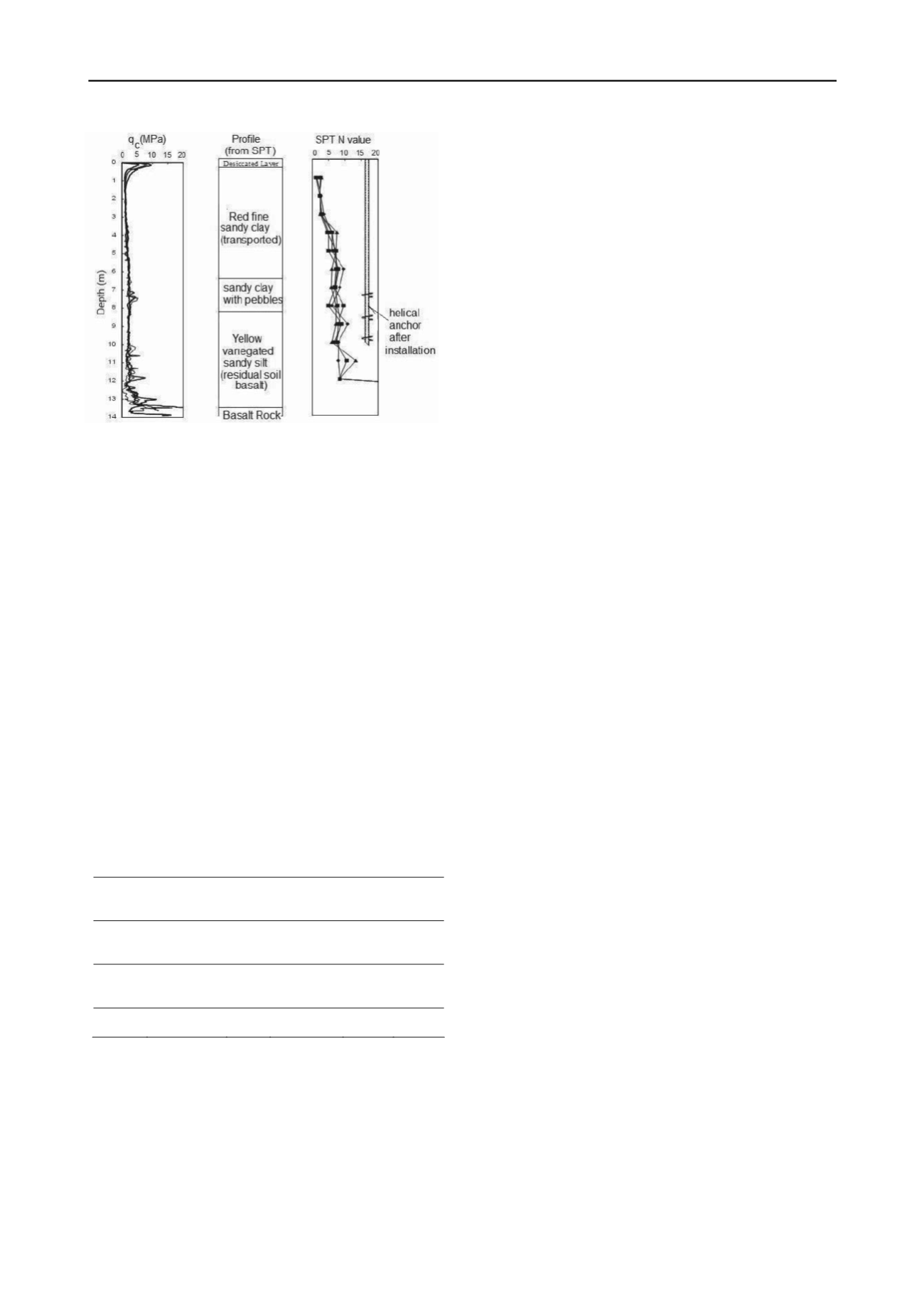
The soil of the CRHEA site is material formed from igneous
rock (basalt) from Serra Geral Formation (Figure 7). The top
layer is a porous colluvial sandy clay with about 8 meters depth.
Below this layer there is a residual soil (from igneous rock)
limited by a thin layer of pebbles. The nature of this tropical soil
is porous and has unstable structure due to the connections
between particles by bonds attributed to soil water suction and
cementing substances.
Figure 7. Soil profile at the CRHEA site.
This difference is explained by the fact that during the
tapered anchor installation, the upper helices pass through intact
soil, differently of the upper helices of cylindrical anchor.
However, during the loading of the both anchors, the both
surfaces of soil mobilized above the plates are disturbed by the
installation of the helices.
3 CONCLUSIONS
Two different types of experimental progr ms were carried on
helical anchors to verify the ffect of the helices configuration
on the anchor uplift capacity. Based on the results of these tests,
the most important conclusions are:
The efficiency of the second helix of helical anchors in sand
decrease with the increase of the relative density and the
helix diameter.
2.2.1 Results of eld ests
All anchors of this field investigation were installed with the
anchor tip at a depth of 10 meters as illustrated in Figure 7.
After installation, tension load tests were carried out on the
anchors shown in Figure 6. More complete details of this
investigation are available in Santos (2012).
The uplift capacity of a triple-helix anchor with tapered
helices is slightly superior then the one of cylindrical
helices, with same average plate diameter in a tropical soil.
4 ACKNOWLEDGEMENTS
The ultimate capacity (Q
u
) of all tests was taken as the load
producing a relative displacement of 10% of the helix average
diameter. Table 3 presents the results of ultimate capacity (Q
u
)
of the tested anchors, and also the fractions of uplift capacity
related the upper plates. Considering the homogeneity of this
site, the fractions of uplift bearing capacity of the second plate
of the multi-helix anchors (F
Qh2
) were calculated by the
difference between the ultimate capacity of anchors with two
helices and of one helix (same bottom helix diameter). The
fractions of uplift capacity due to the third plate (F
Qh3
) of three-
helix anchors were calculated by using the same procedure.
The authors wish to thank FAPESP (Fu dação de Amparo à
Pesquisa do E tado de São Paulo) project n
o
2010/19039-6, and
the
international
Cooperation
USP/Cofecub
project
n
o
2012.1.678.1.9.
5 REFERENCES
Clemence, S.P., Crouch, L.K., and Stephenson, R.W. 1994. Prediction
of uplift capacity for helical anchors in sand. In Proceedings of the
2nd Geotechnical Engineering Conference, Egypt. Vol. I: 332–343.
The comparison between the double-helix anchor A2
(cylindrical) and B2 (tapered) shows that the contribution of the
second helix to the total capacity is better for tapered
configuration. The second helix of the anchor B2 is larger than
the bottom helix, and installed in a less disturbed soil layer
compared to the second helix of the cylindrical anchor A2.
Kulhawy, F.H. 1985. Uplift behaviour of shallow soil anchors — an
overview. In Uplift Behaviour of Anchor Foundations in Soil.
ASCE: 1–25.
Lutenegger, A.J. 2009. Cylindrical Shear or Plate Bearing? – Uplift
Behavior of Multi-Helix Screw Anchors in Clay. Contemporary
Issues in Deep Foundations, ASCE: 456-463.
Table 3. Contribution of the upper plates to the total anchor uplift
capacity.
Lutenneger, A.J. 2011. Behavior of multi-helix screw anchors in sand.
In Proceedings of the 14th Pan-American Conference on Soil
Mechanics and Geotechnical Engineering
, Toronto, Ont. [CD
ROM].
Mitsch, M.P., and Clemence, S.P. 1985. Uplift capacity of helix anchors
in sand. In Uplift Behaviour of Anchor Foundations in Soil, ASCE:
26-47.
Anchor
Helic s
diameters
(mm)
Q
u
(kN)
F +
Qh1
Q
s
fraction
(%)
F
Qh2
(%)
F
Qh3
(%)
A1
200
14,5
100.0
A2
200/200
25
58.0
42.0
A3 200/200/200
36
40.3
29.2
30.6
B1
150
13,5
100.0
B2
150/200
31
43.5
56.5
B3 150/200/250
39
34.6
44.9
20.5
C2
200/250
48
30.2
69.8
C3 200/250/300
57
25.4
58.8
15.8
ooney, J.S., Adamczak, S.J, and Clemence, S.P. 1985. Uplift Capacity
of Helix Anchors in Clay and Silt. Uplift Behaviour of Anchor
Foundations in Soil, ASCE: 48-72.
Sakr, M. 2009. Performance of helical piles in oil sand.
Canadian
Geotechnical Journal
46: 1046–1061.
Santos, T.C. 2012. The effect of helices configuration on the uplift
capacity of helical piles in a tropical soil. Dissertation (master's
degree) – Escola de Engenharia de São Carlos, Universidade de São
Paulo, São Carlos.
However, from the comparison between the third helix
contribution to the total capacity (F
Qh3
) of three-helix anchors
A3, B3, and C3, it could be observed that the efficiency of the
third helix decreases with the third plate diameter, even for the
tapered anchors. A similar trend was observed in the centrifuge
tests presented in this paper. However, further investigation is
needed to confirm this behaviour.
Terzaghi, K. 1943.
Theoretical soil mechanics
. John Wiley & Sons,
New York.
Tsuha, C.H.C., Aoki, N., Rault, G., Thorel, L., and Garnier, J. 2007.
Physical modeling of helical pile anchors.
International Journal of
Physical Modelling in Geotechnics
7(4): 1–12.
Tsuha, C.H.C., Aoki, N., Rault, G., Thorel, L., and Garnier, J. 2012.
Evaluation of the efficiencies of helical anchor plates in sand by
centrifuge model tests.
Canadian Geotechnical Journal
49: 1102–
1114.
2.2.2 Cylindrical and tapered helices
The results of the final installation torque and the uplift capacity
of helical anchors ith same average plate diameter (A3 and
B3) were compared. From this comparison it was found that the
gain in uplift capacity for the tapered anchor is about 8%.
However, to install the tapered model, it was necessary to apply
a torque 20% larger than the needed to install the cylindrical
model.


