2895
Technical Committee 212 /
Comité technique 212
the Q
h
results of double-helix and single-helix anchors with
same helix diameter and tip depth. A similar procedure was
used to calculate the Q
h
fractions of middle and upper helical
plates of triple-helix anchors, and these results are included in
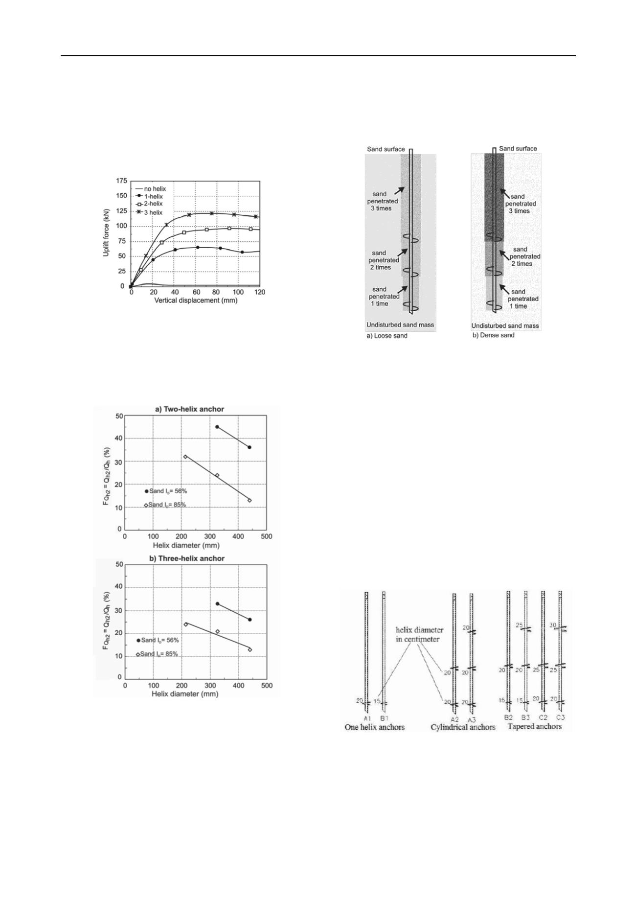
Tsuha et al. (2012). Figure 4 shows the fractions of helix
bearing capacity related to the second helix (F
Qh2
) of the double
and triple-helix anchors tested in this investigation.
Figure 3. Load–displacement curves of tensile tests performed on model
anchors of 214mm helix (prototype) diameter in container 2.
The results of tests performed on the model anchors with
helix diameter of 214 mm in the looser sand are influenced by
some local heterogeneity. For this reason, the contribution of
the second helix of the anchors P2 installed in the container 1,
was not shown in Figure 4.
Figure 4. Relationship between the second helix contribution to total
helix bearing capacity and the helix diameter of a) double helix and b)
triple-helix anchors (Tsuha et al. 2012).
2.1.2 Efficiency of the second helix
Figures 4 shows that the efficiency of the second helix, of
double and triple-helix anchors, depends linearly of the helix
diameter, and also of the initial sand relative density (I
D
).
2.1.3 Effect of sand compactness
The results of Figure 4 illustrate the influence of the relative
density on the efficiency of the second plate of multi-helix
anchors installed in sand. According to Tsuha et al. (2012), for
dense sand, the difference in compactness between the sand
penetrated by a helix one time and the sand penetrated two or
three times is significant. Differently, for the looser tested sand,
after anchor installation, the final relative densities of the sand
above the three helices are similar. This hypothesis is detailed in
Figure 5.
Figure 5. Hypothesis for sand disturbance after installation of a three-
helix anchor: (a) loose sand; (b) dense sand (Tsuha et al. 2012).
2.1.4 Effect of helix diameter
The efficiencies of the second plates of the tested anchors
decrease with the increase in helix diameter, as observed in
Figure 4. This fact indicates that the effect of the helical anchor
installation on the sand mass is more significant for helical
anchors with larger plates. As the region of disturbed sand
around the cylinder circumscribed by the anchors helices after
installation is larger for larger helix diameter (increases with the
helix diameter), the failure surface mobilized during the anchor
loading is more distant from the undisturbed sand.
Consequently, the efficiency of the second helix of cylindrical
helical anchors decreases with the increase in diameter.
2.2 Field testing program
Eight helical anchors (Figure 6), with different configurations
(multi-helix anchors with the same plate diameter and with
increasingly larger diameter helices up the central shaft) were
installed and tested at the CRHEA site of the São Carlos School
of Engineering, São Carlos city, Brazil.
Figure 6. Prototype helical anchors tested at the CRHEA site.
The soil of the CRHEA site is material formed from igneous
rock (basalt) from Serra Geral Formation (Figure 7). The top
layer is a porous colluvial sandy clay with about 8 meters depth.
Below this layer there is a residual soil (from igneous rock)
limited by a thin layer of pebbles. The nature of this tropical soil
is porous and has unstable structure due to the connections
between particles by bonds attributed to soil water suction and
cementing substances.
Figure 7. Soil profile at the CRHEA site.


