2878
Proceedings of the 18
th
International Conference on Soil Mechanics and Geotechnical Engineering, Paris 2013
reached the first dense sand layer at about 28.5 m. deep. The
second very dense sand where the pile tip of the building is
seated is found at about 46 m. deep below ground surface. Table
1 presents the soil condition and the engineering properties.
Table 1. Soil conditions and engineering properties.
Depth
(m.)
Soil
Description
t
Su N Eu
E’
0 -
12.5
Soft Clay
16.0
15
-
8750
-
12.5 -
15.0
Medium
Stiff Clay
16.5
40 -
18000
-
15.0 -
20.0
Stiff to
Very Stiff
Silty Clay
19.0
-
12 85000
-
20.0 -
28.5
Hard Clay
20.0
-
35
300000
-
28.5 –
39.0
Dense Silty
Sand
20.0
-
40
80000
39.0 –
46.0
Hard Silty
Clay
20.0
-
45
-
-
46.0 –
65.0
Very Dense
Silty Sand
20.0
-
>50
-
-
Note:
t = Total Unit Weight (kN/m
3
)
Su = Undrained Shear Strength (kN/m
2
)
N
= SPT N-Value (Blows/ft)
Eu, E’ = Undrained and Drained Young’s Modulus (kN/m
2
)
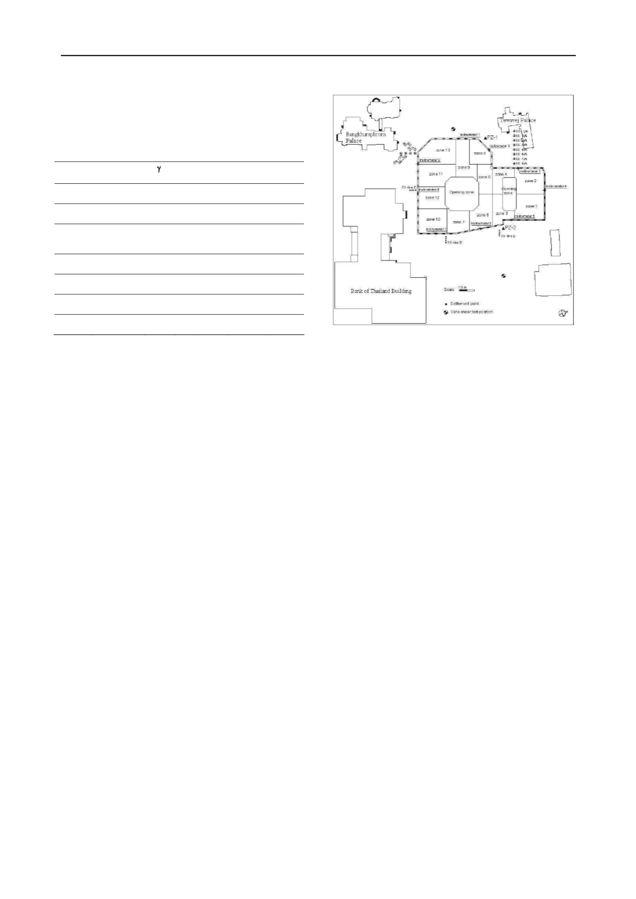
3 PROJECT DESCRIPTION
The basement design and construction of the new head office of
bank of Thailand aims to solve the problem of car park from
both staff as well as visitors. The surface area of excavation is
approximately 10790 m
2
with 5 m. and 10 m. away from
Tewavej Palace and Bangkhumphrom Palace accordingly as
shown in Fig 2. The Tewavej Palace and Bangkhunphrom
Palace are the historical palace constructed by brick and bearing
wall seated on shallow foundation. In order to minimize the
influence on these two palaces, the basement of BOT was
designed to be constructed by top-down construction method
which has been used only in Bangkok city restricted area such
as the subway station of MRT project.
The diaphragm wall (D-Wall) of 1.0 m. thick and 20 m. deep
was designed as the temporary wall for 15.8 m. deep excavation
and used as permanent wall at the final stage. Five basement
floors consist of F
1
,P
1
,P
2
,P
3
and P
4
floor at -1.20 m., -4.70 m.,
-7.70 m., -10.70 m., and -13.70 m. deep respectively as
illustrated in Fig 3.
The top-down construction method was started by casting
the first basement F
1
at -1.20 m. then moving to third basement
floor (P
2
) at -7.70 m. and constructing the fifth basement floor
and mat foundation at -13.70 m. deep as shown in Fig 3.
Loading of the permanent basement floor during construction
was transferred through the stanchion at the centerline of the
column which was installed into the bored pile during
construction of the bored pile.
Figure 2. The BOT project plan view.
4 INSTRUMENTATION
The head office of BOT was constructed in the large area of
more than 10790 m
2
; therefore, the excavation area for top-
down construction was divided into 13 zones as presented in
Fig 2. Two large opening zones were provided for excavation
work. The excavation at the deeper basement required to
excavate step by step from far corner to the opening zone where
the excavated soil was moved out of the project area. For safety
reason and to monitor basement wall behavior, the full scheme
of instrumentation was installed at the palaces on the ground
surface and in the diaphragm wall as shown in Fig 2 and Table
2.
5 ANALYSIS AND DESIGN OF DIAPHRAGM WALL
The analysis and design of the diaphragm wall was carried out
by means of the FEM. The construction sequence was simulated
in the FEM analysis. The sequence of basement construction
consists of 8 steps as follows:
1.Excavating to -1.75 m. deep and casting lean concrete.
2.Casting the first permanent basement floor at -1.20 m.
(thickness 0.45 m.)
3.Excavating to the third basement floor at -8.10 m. deep and
casting lean concrete.
4.Casting the third permanent basement floor at -7.70 m.
(thickness 0.30 m.)
5.Excavating to the fifth basement floor (base slab) at -15.60 m.
deep and casting lean concrete.
6.Casting the fifth basement floor (base slab) at -13.70 m.
(thickness 1.30 m.)
7.Casting the permanent fourth basement floor at -10.70 m.
(thickness 0.30 m.)
8.Casting the permanent second basement floor at -4.70 m.
(thickness 0.30 m.)
The detail of construction sequence is presented in Fig. 4.
The analysis and design of the diaphragm wall for 15.6 m.
deep excavation were carried out by FEM. As the basement
constructed in soft clay layer, the undrained concept based on
bi-linear Mohr-Coulomb failure theory was used for FEM
analysis. The Young’s modulus (Eu) was used in terms of an
undrained shear strength (Su) of Eu/Su = 500 and 1000 for soft
clay and stiff clay respectively (Teparaksa, 1999b). The value of
Young’s modulus is also presented in Table 1.
The Young’s modulus or shear modulus (G) of clay depends
on the shear strain of the system as proposed by Mair (1993) as


