2868
Proceedings of the 18
th
International Conference on Soil Mechanics and Geotechnical Engineering, Paris 2013
(1)
The main conclusions following the load test were as fol-
lows:
• There is no evidence of any detrimental effects from the
cavity feature on the pile capacity.
For the development of shaft resistance the following expres-
sion may be tentatively used (Steenfelt & Abild, 2011):
• Both the shaft and the toe capacity are far from being ex-
hausted at the maximum bi-directional load of 40.1 MN.
(2)
where
ult,s
(shaft resistance) is of the order 3-10 mm.
Based on the lower bound characteristic ultimate shaft fric-
tion resistances indicated in Table 1 and
ult
= 5.5 mm a total
shaft resistance above the O-cell for the 26.1 m pile of 38.8 MN
is found based on the mobilisation ratios inferred from Eq. (2).
Average displacements in Marlstone, Marl 2, Marl 1 and fill,
based on the tell tale measurements, have been used in this as-
sessment. The corresponding ultimate shaft resistance at 100%
mobilisation is 54.2 MN.
• A maximum characteristic toe bearing stress of 11 MPa was
conservatively assumed in the design. This stress was al-
most reached in the test but at a toe displacement of only
some 25 mm, corresponding to a low degree of mobilisation
(of the order 24%). Thus, the cavity remediation works, in-
cluding the reinforcement of the weathered Limestone, has
been successful and allows for a high toe bearing capacity
in ULS (cf. Figure 11).
• Extrapolation of shaft and toe resistances to 200 mm toe
displacement and >5 mm shaft/soil displacement show ca-
pacity at or above the structural capacity of the concrete pile
of approximately 110 MN (at the 7 days compressive con-
crete strength of 33.5 MPa).
For the toe resistance and
mob
=
25.7 mm full development
of 9.5 MN shaft resistance is assumed on the lower 1 m pile
(
mob
>
ult
). This means that the mobilised toe resistance is 30.6
MN and by application of Eq. (1) an ultimate toe resistance of
85.5 MN may be deduced.
Based on the thorough investigation of the cavity feature and
the closely monitored remediation work it was possible to suc-
cessfully conclude the foundation works for the Pylon P4 and
start the casting of the Pylon as seen in Figure 15.
Thus, based on conservative estimates for the characteristic
shear strength of the layers involved an ultimate capacity of the
P4/3 pile of almost 140 MN is inferred. This would be close to
the characteristic structural capacity of the pile as it corresponds
to a maximum characteristic stress of 44.6 MPa at the pile toe.
Considering that conservative parameters have been applied
it is concluded that the pile has more than sufficient capacity
and that there is no reduction of capacity from the presence of
the cavity feature or the weathered Limestone below the toe of
the pile
7 SUMMARY & CONCLUSION
The recorded cavity feature below the foundation for Pylon P4
necessitated remedial measures. At the same time the Contrac-
tor preferred pile toes at a higher level, above the cavity feature,
in order to reduce construction time. These issues were ad-
dressed by:
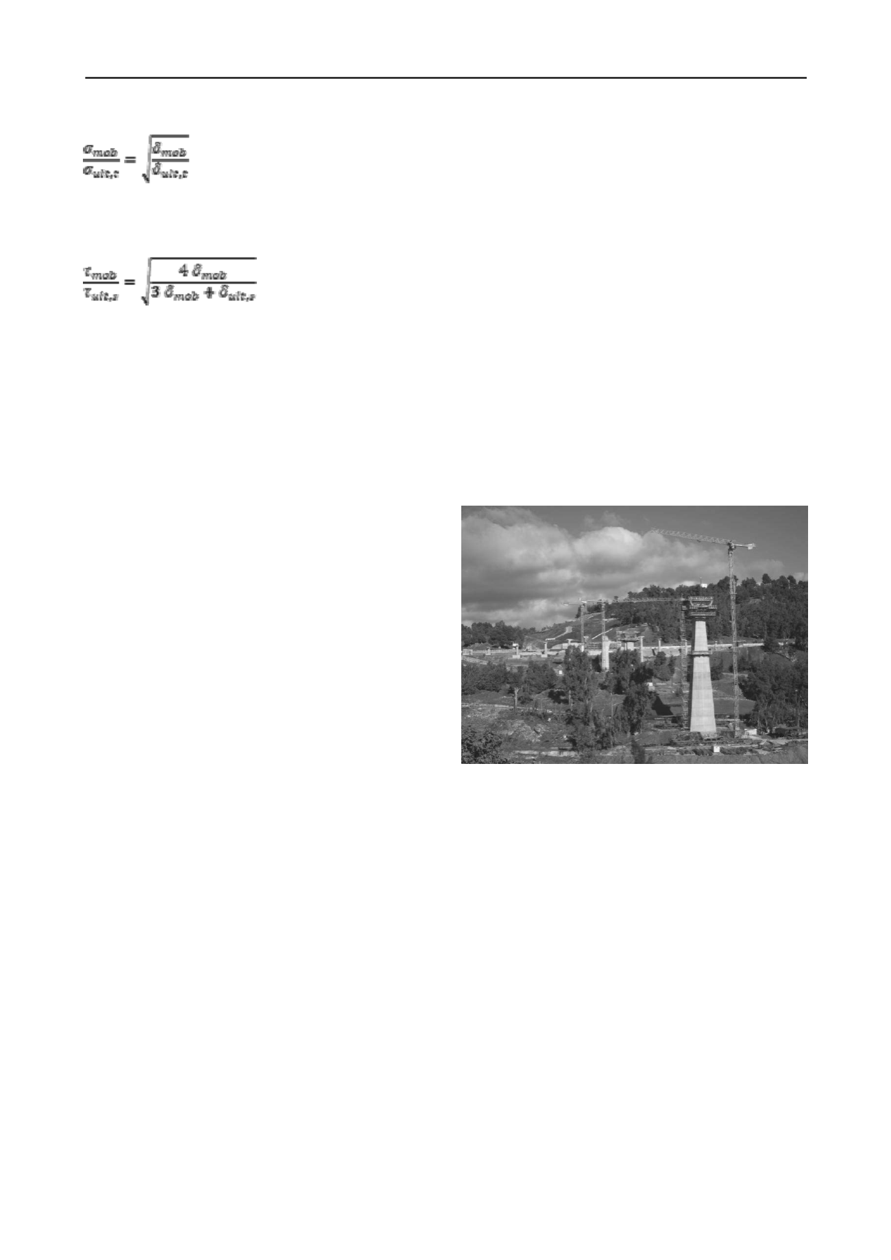
Figure 15. Status of P4 construction December 2012
• the installation and grouting of five 12 m long reinforcing
elements ("micro piles") from 0.14 to 0.78 m distance below
the pile toe level and into the intact Limestone
8 ACKNOWLEDGEMENTS
• pressure grouting of 20 primary and 26 secondary grout
holes over and slightly beyond the foot print of the P4 Pylon
• load testing of Pile P4/3 situated at the most onerous posi-
tion over the recognised cavity feature
The authors gratefully acknowledge fruitful discussions and in-
teraction with the Contractor's site team in Constantine as well
as the permission by the Contractor Andrade Gutierrez and the
Designer COWI to publish the paper.
It was concluded that the cavity feature was not a consistent fea-
ture but was concentrated around piles 3, 9, 11, 12 and 14. Even
if some additional cavity feature should exist to the west of pile
8 or to the north of pile 12 it is entirely unlikely that this would
have any detrimental effect on the bearing capacity of the pile
group.
9 REFERENCES
Fleming, W.G.K. 1992. A new method for single pile settlement predic-
tion and analysis.
Géotechnique 42
, No. 3, pp 411-425.
Fleming, W.G.K., Weltman, A,J. Randolph, M.F., Elson, W.K. 2009.
Piling Engineering, Third ed
., Taylor & Francis.
The remediation measures were therefore deemed successful
and required no further tertiary grouting to be carried out.
Steenfelt, J.S.. and Abild, J. 2011. Capacity of rock sockets in weak
Mud/Siltstone.
Proceedings XVth European Conference on Soil
Mechanics and Geotechnical Engineering,
12-15 Sept. 2001


