2864
Proceedings of the 18
th
International Conference on Soil Mechanics and Geotechnical Engineering, Paris 2013
The borehole B4/03 at the location of Pile P4/3 indicates a
soil profile as summarized in Table 1.
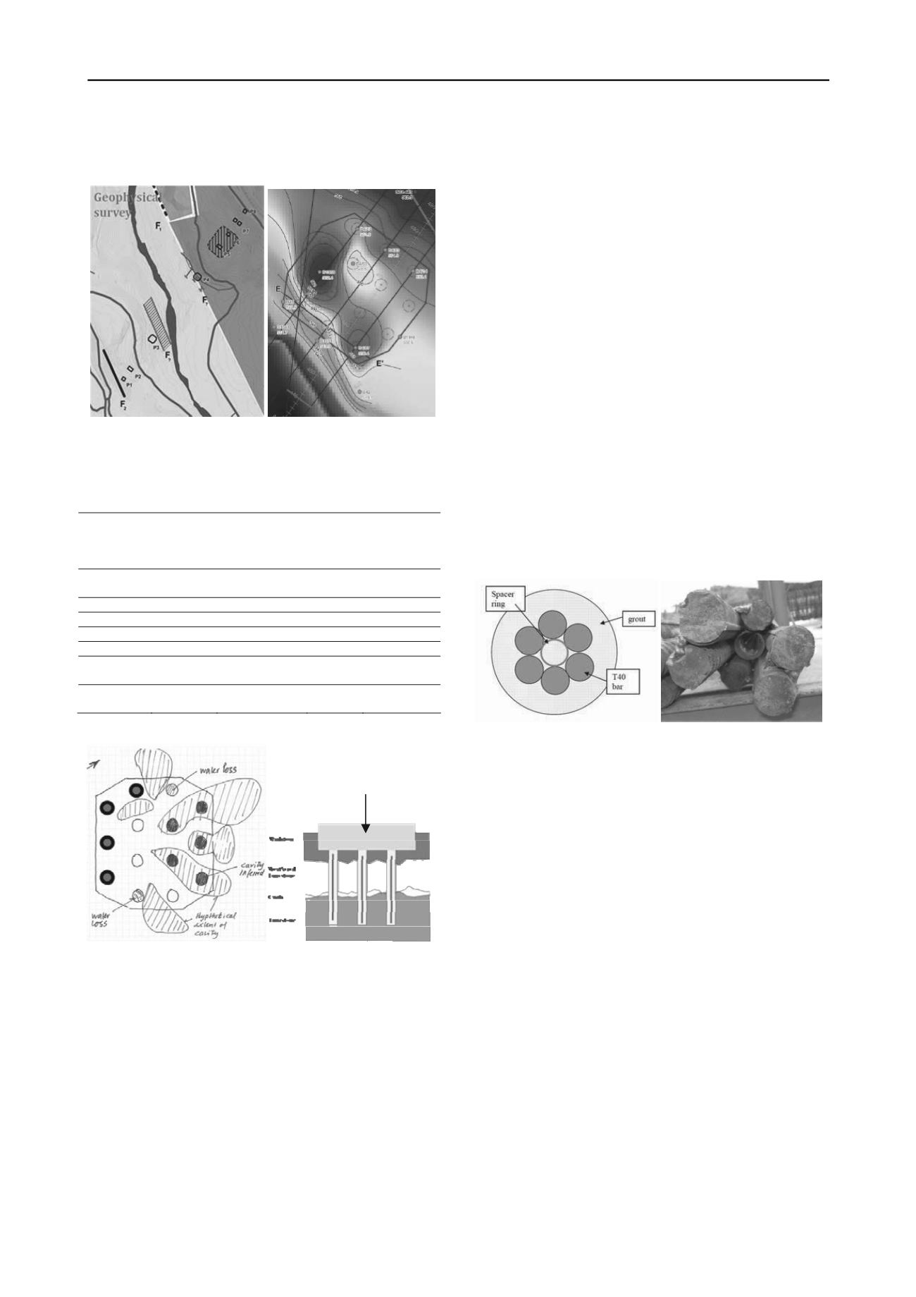
Figure 2. Geophysical survey and contour plot of Limestone surface
based on boreholes (F
1
denotes the main fault at P4 location)
Table 1. Soil profile at borehole B4/03 (at pile 4/3) and assumed lower
bound characteristic soil parameters (
= 0.37 c
u
assumed for design in
oils and formula (4.25) from Fleming et al. 2009 in rock).
s
Soil/rock
layer
Top level
1)
(m)
Undrained
shear strength
c
u
(kPa)
Shaft
friction
(kPa)
Toe bearing
capacity
(MPa)
Fill from
ground
+586.6
61
23
Marl 1
+579.9
141
52
Marl 2
+570.4
335
124
Marlstone
+565.3
6750
1520
11
Pile toe
+559.5
Weathered
Limestone
+557.8
3500
Limestone
(intact)
+548.3
9000
1)
Datum in Fuse 32
Figure 3. (a) Hypothetical extent of cavity feature (piles with bold out-
line were drilled into Limestone); (b) Schematic cross section at pile toe
in Marlstone with pre-drilling holes below pile toe.
The unconfined compressive strength in the weathered Lime-
stone (5 to 9 m layer between Marlstone and top of intact Lime-
stone) had to be re-assessed from dried out samples and hence
the average value of
c
= 13.1 MPa (7 MPa as 95% lower frac-
tile) was deemed conservative.
The strength of the Marlstone was
c
= 13.5 whereas
c
>>
18 MPa for the Limestone, i.e. above the strength of the con-
crete.
The toe bearing for the Marlstone was conservatively calcu-
lated as for a soil (11 MPa) as opposed to 45 MPa if rock pa-
rameters were used.
However, the drilling subcontractor TREVI experienced exces-
sive time delays when drilling the 2 m diameter bored piles, 42
to 46 m long, into the Limestone, even after executing five
Ø178 mm pre-drilling holes to the pile toe level within the foot
print of each pile.
Moreover, the exploratory boreholes indicated the presence
of cavities within the Limestone, at the base of the upper weath-
ered zone and with heights up to 1 m.
The indicators were severe water loss and/or a sudden drop
of the drill string.
Based on the observations the extent of the cavity feature
was hypothesized as shown in Figure 3.
3 REMEDIATION AND MONITORING STRATEGY
The existence of the five Ø178 mm pre-drilling holes to the
level of intended pile toe in Limestone turned out to be both a
blessing and a curse. By re-opening the holes it would be possi-
ble to insert a "reinforcement" to transfer the load across the
cavity feature but the holes at the same time prevented pressure
grouting of the cavity as un-grouted holes would function as
venting holes.
The solution adopted consisted in inserting a 12 m long steel
reinforcing assembly composed of 6 Nos. of T40 mm rein-
forcement bars tack welded together around a central spacer
ring into each pre-drilled hole. This solution was chosen in or-
der not to cause delays by delivery to Africa of the preferred
Ø90 mm GEWI piles and to utilize on site material. The rein-
forcement provided by the T-bars corresponds by and large to
the reinforcement in the lower part of the Ø2 m bored pile.
Figure 4. (a) Cross section through pre-drilling hole with assembly of T-
bars; (b) Photo of T-bar assembly with spacer ring
The rationale of the solution is to transfer the axial load from
the pile toe in Marlstone through the weathered Limestone and
the cavity feature into the competent Limestone without risking
excessive (differential) vertical displacement of the piles. Grout
around the reinforcing assembly ensures stability of the rein-
forcement throughout the 12 m length. The reason for choosing
this solution was that the pre-drilled holes were already avail-
able and it was not considered feasible to pressure grout the
very localised weathered zones in the Limestone when grouting
from just a few boreholes. The different degree of weathering
across the foundation footprint could cause different settlement
behaviour for individual piles, especially as the weathered zone
would be directly below the pile toe where the loads are most
concentrated.
Pile toe
The sequence of the reinforcement installation is: (i) re-open
a pre-drilling hole, (ii) install 12 m long reinforcement assem-
bly, with tremie pipe through the centre, so the top level is ap-
proximately 0.5 m below pile toe level, (iii) grout to the pile toe
level allowing grout to permeate into potential cavities around
the hole.
Grout of relatively high viscosity (Marsh viscosity 35- 50
sec.) was used. It consisted of Portland cement 42.5 with w/c ra-
tio of 0.45 and thinner adjuvant type Rheobuilt with w/a ratio of
0.5 - 1.0%. Settling at 4 h < 5%. It would be expected that the
grout could travel some 3-5 m away from the pre-drilling hole.
However, as the cavity (cavities) may have a considerable hori-
zontal extent also outside the foundation footprint as visualized
in Figure 3a it was considered a must to also perform pressure
grouting (of cavities) to ensure the design capacity of the pile


