2856
Proceedings of the 18
th
International Conference on Soil Mechanics and Geotechnical Engineering, Paris 2013
The soil medium is assumed to be an elastic, isotropic
continuum, homogeneous within each layer, with Lame’s
constants
G
s
and
s
. There is no slippage or separation between
the pile and the surrounding soil or between the soil layers. The
pile behaves as an Euler–Bernoulli beam with a constant
flexural rigidity
E
p
I
p
.
3 ANALYSIS
3.1
Soil Displacement Field
A separable variable technique is used to define the horizontal
displacement fields in the soil, and the soil displacement
u
z
in
the vertical direction is assumed to be negligible. The horizontal
displacements for rectangular and circular piles are given by
( ) ( ) ( ),
0
for rectangular piles
( ) ( ) cos ,
( ) ( )sin for circular piles
x
x
y
y
r
r
u w z x y u
u w z r
u w z r
(1)
where
w
(
z
) is a displacement function (with a dimension of
length) varying with depth
z
that describes the pile deflection,
x
(
x
) and
y
(
y
) are dimensionless displacement functions
varying along the
x
and
y
directions of the Cartesian coordinate
system used for the rectangular-cross section pile, and
r
(
r
) and
(
r
) are dimensionless displacement functions varying along
the
r
and
directions of the cylindrical coordinate system used
for the circular-cross section pile (Figure 1). The dimensionless
displacement functions describe how the displacements in the
soil mass (due to pile deflection) decrease with increase in
horizontal distance from the pile. These functions are set to
unity at the pile-soil interface, which ensures perfect pile-soil
contact, and are set to zero at infinite horizontal distance from
the pile center, which ensures that the displacements in the soil
due to the laterally loaded piles decrease as the horizontal
distance from the pile increases.
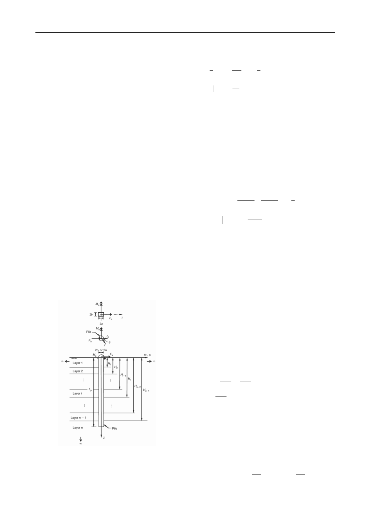
Figure 1. Laterally loaded pile in a layered elastic medium (Modified
after Basu and Salgado 2008 and Basu et al. 2009)
3.2
Potential Energy and its Minimization
The total potential energy of the pile–soil system, including
both the internal and external potential energies, is given by:
2 2
2
0
0
0
1
1
2
2
p
s
L
p p
a
a
z
z
d w
E I
dz
d
dz
dw
F w M
dz
mn mn s
(2)
where
w
is the lateral pile deflection;
mn
and
mn
are the stress
and strain tensors in the soil, respectively (summation is implied
by repetition of the indices
m
and
n
); and
s
represents the soil
domain surrounding the pile that extends to infinity in the
horizontal directions and from 0 to +∞ in the
z
direction, but
excludes the volume occupied by the pile. The first integral in
Eq. (2) represents the internal potential energy of the pile, while
the second integral represents the internal potential energy of
the soil continuum. The remaining two terms represent the
external potential energy.
The principle of minimum potential energy (
= 0) is used
to obtain the differential equations governing the equilibrium
condition of the pile-soil system:
2
2
2
2
0
0
0
1
2
0
p
s
z L
p p
mn mn
s
z
a
a
z
z
d w z d w z
E I
dz
d
dz
dz
dw z
F w z
M
dz
(3)
The strain-displacement relationship for infinitesimal strains
and the elastic stress-strain relationship, given by
2
mn
s mn
s kk mn
G
(4)
are used in Eq. (3) to express the first variation of the total pile-
soil potential energy in terms of the soil elastic constants and
the displacement functions described in Eq. (1). Thus Eq. (3)
contains the first variations of the displacement functions
w
,
x
and
y
for rectangular pile and the first variations of the
displacement functions
w
,
r
(
r
) and
(
r
) for circular pile. Since
these variations are independent, the terms associated with each
of these variations can be individually equated to zero, which
produces the differential equations and boundary conditions of
the displacement functions.
3.3
Pile deflection
The pile deflection equations corresponding to the
i
th
soil layer
for both circular and rectangular piles is given by:
4
2
4
2
2
2
0 0
0
i
i
p p
i
i i
i
i
i i
p
d w d w
p
E I
t
k w
z
dz
dz
d w t
k w
z L
dz
L
(5)
where, for rectangular piles:
2 2
,
2 2
,
4 0
s i
x y
i
s i
x y
p
G
dxdy ab
z
t
G
dxdy
z L
p
L
(6)
2
2
2
2
,
,
,
(
2 )
y
x
i
s i
s i
y
s i x
d
d
k
G
G
dx
dy
dxdy
(7)
and, for circular piles:


