2850
Proceedings of the 18
th
International Conference on Soil Mechanics and Geotechnical Engineering, Paris 2013
.
Notice that the maximum loads were around 8000 kN and
settlements were in between 1.4 mm and 1.50 mm for the
maximum load imposed. At the service load is expected a
settlement lower than 0.6 mm.
5 REFERENCES
Bermingham P. and Janes M., 1989. Innovative Approach to Load
Testing of High Capacity Piles, Proc. Int. Conference on Piling
and Deep Foundations, London, pp. 409-413.
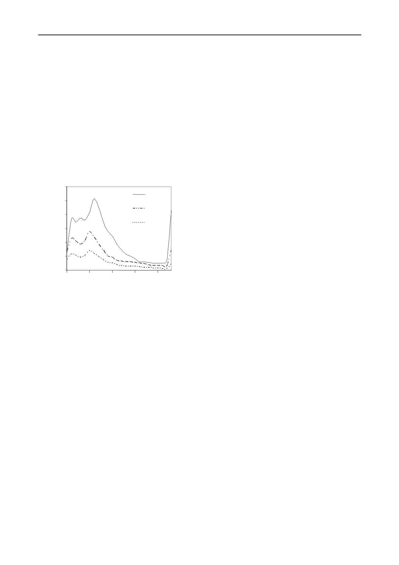
The piles were also modeled by using the wave equation
model formulated by Smith (1960). The pile shaft was divided
in sections of one meter ant the soil was modeled as spring and
dashpots. The dynamic constants were varied until the best
approximate of the model to the measurements were obtained.
Figures 7 and 8 show the agreement of the modeled pile to the
measurements. The distribution of reaction forces along the pile
shaft is shown in Figure 11. It seems that most of the load is
taken by the shaft an only 900 kN are taken by the tip at the
maximum load of the test performed. The behavior of pile-soil
systems corresponds to a quasi elastic phase with little plastic
deformations.
Goble G. and Likins G., 1996. On the Application of PDA Dynamic
Pile Testing, Proc. 5th Intern. Conf. on the Application of Stress
Wave Theory to Piles, Orlando, FL.
Matsuzawa K., Nakashima Y. and Matrsumoto T., 2008. Spring
Hammer Rapid Load Tests Method and Its Validation, Proc. of
the 2nd BGA International Conference on Foundations, Brennan
A. And Knappedt J. Ed., pp.224-234.
Miyasaka T., Kuwabara F., Likins G. and . Rauche F., 2008. Rapid
Load Test on High Bearing Capacity Piles”, Science Technology
and Practice, Dos Santos J. Ed., pp. 5001-5006.
Schellingerhout A.J.G. and Revoort E., 1996. Pseudostatic Static Pile
Load Tester, Proc. Of 5th international Conference of Stress
Wave Theory to Piles, Orlando, pp.1031-1037.
Figure11. Distribution of reaction forces along the pile shaft
obtained from the solution of the wave equation for different drop
height of the mass.
4 CONCLUSIONS
The conclusions of the work presented here can be
summarized as follow:
a) The pseudostatic test can be performed for most piles
using a proper design of the cushion system and falling
weight.
b) The falling weight method is advantageous respect to
most other pile loading test since it can be performed
much easier, at lower costs and at higher productivity
per day.
c) The pseudostatic test procedure has also the advantage
that can be interpreted as the conventional static test
and also using the Smith´s wave equation.
d) There is a need to compare the results from pseudostatic
tests and static tests, however, since the pseudostatic
test is physically identical to the Statnamic method, the
well established comparison between Statnamic and
static can be extended to the pseudostatic falling weight
test.
Smith, E. A. L. 1960. Pile Driving Analysis by the Wave Equation,
Journal of the Soil Mechanics and Foundations Division , ASCE,
Vol. 86, No. SM4, Proc. Paper 2574, pp. 35-61, Agosto, 1960
1200
0
200
400
600
800
1000
Reaction Force [kN]
2.8m
2.6m
2.2m
16
21
1
6
11
Depth [m]


