2848
Proceedings of the 18
th
International Conference on Soil Mechanics and Geotechnical Engineering, Paris 2013
Figure 2: Model for the soil pile interaction in the peudoestatic model.
To increase the application time of loading, a high strength
resilient material is required to be placed on the head of the pile
in the area of impact. Assuming that the load is obtained by a
falling mass of approximately 10% of the ultimate capacity of
the pile (Fu) and also considering the charging triangular
diagram of Figure 3, then:
g
h
F
gh
g
F
F
gh m t
u
u
u
21.0
2 1.0
2
50
(3)
Where
h
is the falling height of the mass
m
. This cinematic
equilibrium equation is an approximation since restitution
forces has been overridden.
The maximum forces that can be exerted on the pile tip
(F
max
) due to the falling mass on a cushion material of elastic
constant
k
e
can be calculated as:
max
max
2
1
z F hgm
(4)
Where z
max
is the maximum deformation of the cushion
material z
max
= F
max
/k
e
. Then, replacing in equation (4),
e
khgm F
2
max
(5)
Being the natural frequency of the mass-cushion system:
e
k
m T
2
(6)
Since t
50
is half of the natural frequency and assuming a
triangular shape of the wave (see Figure 3):
e
e
k
m
t
k
m
3
2
50
(7)
Figure 3: Simplified model of the stress pulse.
Equations (5) to (7) allows to evaluate the magnitude of
the mass and the falling height to obtain a maximum force F
max
according to the elastic constant
k
e
of the cushion material.
From Figure 2, the equilibrium equation can be derived
as:
(8)
aMM F F F
p
s
k c d
)
(
Where
M
s
and
M
p
are the mass of the pile and the soil
respectively and
a
is the acceleration of the movement.
Equation (8) can be rewritten in terms the resistant forces as a
function of the dynamic parameter
F
c
= c v
, and
F
k
= k u
, being
u
and
v
the displacement and velocity of displacement
respectively:
(9)
aMM uk vc F
p
s
d
)
(
Dynamic Force
Equation (9) allows determine dynamic influence on the
measured force at the point of where the velocity becomes zero
and thereafter correcting the measured force by the dynamic
effect.
Fd
Mp
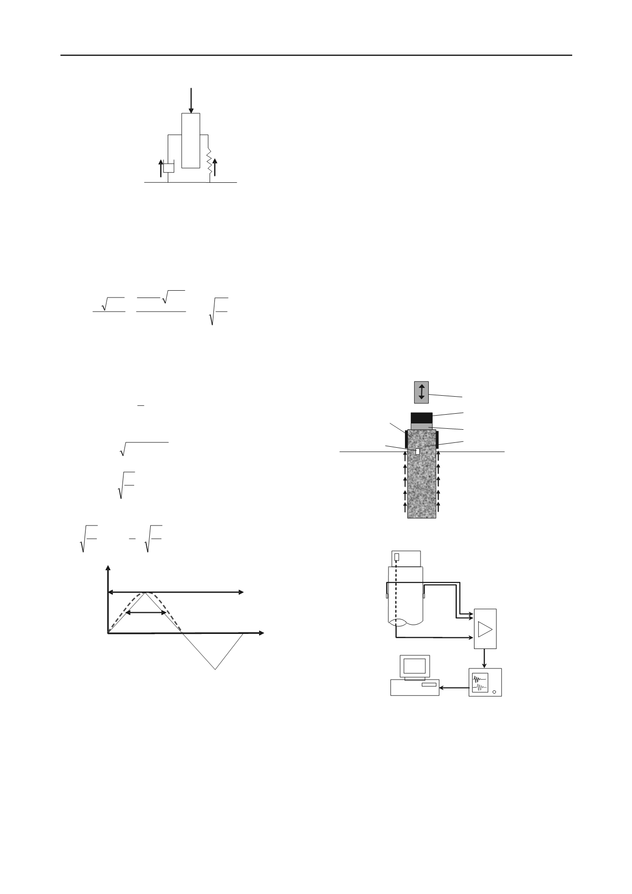
2 TESTING PROCEDURE.
Figure 4 and 5 sketch the testing setup and electronic devices
used for the pseudoestatic load test. This loading design
generates a time-controlled load which will depend on the
magnitude and height of the falling mass, and geometry and
elastic properties of the elastomeric cushion included between
the mass and head of the pile. The force pulse is captured by a
load cell placed below the cushion. The displacement of the pile
is obtained from the double integration of the signals captured
by two accelerometer placed on the shaft and below one
diameter from top of the pile. The weight of the mass to be used
ranges between 5% and 10% of the servicebility capacity of the
pile. The test requires the continuous increment of the height of
drop of the mass. The output of the conditioners is then
digitized by the dynamic analyzer and conveniently stored for
subsequent laboratory analysis. In addition to the equipment
shown, a proximeter is placed to capture displacements and
permanent settlement of the pile. The maximum testing load is
obtained when a permanent displacement is generated or until
the 50% of the service load is reached.
Figure 4. Testing setup for the pseudoestatic load test.
Figure 5. Testing electronic devices used for the pseudoestatic load test.
The impact mass can be made at the site usually employing a
concrete slab or a steel casing filled with concrete depending on
its size. For the purpose of centering the load, steel bars are used
as guides for obvious safety reasons and ensuring the impact of
the mass be centered avoiding the generation of moments. For
the purpose of preventing the damage of the pile by the
application of impact on the mass, the shaft is increased (1.5 to
2 times the diameter) by means of a steel case of the same
diameter of the shaft. In all cases, the accelerometers must be
positioned below this extension or in a window made on it. The
Spring
+
Force
Ms
Damping
Force
F
c
F
k
c
k
Amplitude (KN)
T
t
50
Time
Falling Weight
Cushion
Pile
Steel
Load Cell
Case
Accelerometer
Load cell
Signal Conditioner
Signal Recorder
Signals from
Signals from load cell
Pile
Signal Processor


