2838
Proceedings of the 18
th
International Conference on Soil Mechanics and Geotechnical Engineering, Paris 2013
0
0.05
0.1
0.15
0.2
0.25
0.3
0.35
0.4
0
5
10
15
U
x max
/ d
1. At stability factor,
N
c
= 4, the unsupported excavation
starts to fail due to the stress of the adjacent building.
2. Contiguous pile wall decreases the lateral soil
displacement between the foundation level of the
adjacent building and the bottom of the excavation.
However, the pile wall does not decrease lateral soil
displacement at the foundation level and below the
bottom of the excavation.
N
c
4.5
2.6
3. Increasing pile diameter (
d
) from 0.3 m to 0.4 m
decreases both lateral deflection and bending moment.
4. Pile wall embedded depth, (
D
) has no obvious effect on
the stability of the supporting system for
N
c
value up to
4. It starts to be more effective for
N
c
> 4 up to
H/D
= 1.
Using
D
values larger than
H/D
= 1 is ineffective and
uneconomic.
D
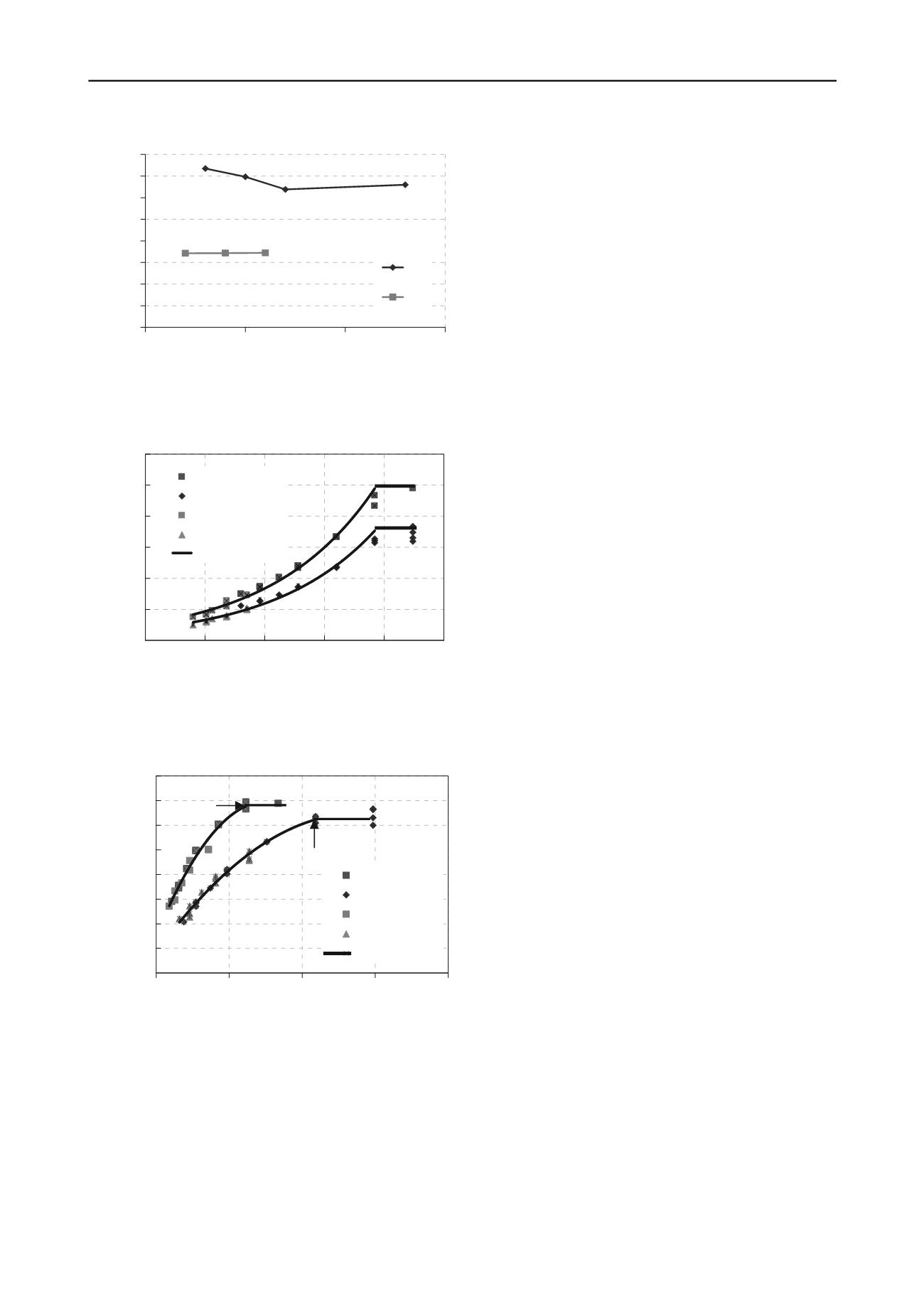
Figure 6. Normalized maximum lateral pile wall displacement versus
pile wall embedded depth
D
, (m)
0
0.1
0.2
0.3
0.4
0.5
0.6
0
1
2
3
4
5
U
x max
/ d
N
c
c=25, d=0.3
c=25, d=0.4
c=50, d=0.3
c=50, d=0.4
Fitting
5. Contiguous pile wall starts to be more effective when
N
c
> 4 as it prevents the unsupported excavation from
failure.
d=0.3 m
6. It is recommended to check the use of connecting beam
at piles head to improve the supporting system for
excavation conditions of
N
c
> 4.
d=0.4 m
5 FUTURE RESEARCH
Figure 7. Normalized maximum lateral pile wall displacement versus
the stability factor
N
c
The present paper is the beginning of an ongoing research on
designing deep excavation. The design of the contiguous pile
wall will be extended to check the stability and safety of the
adjacent building. Also, using braced excavation will be
considered. A method will be derived to predict the earth
pressure on the contiguous pile wall.
6 REFERENCES
Chen L.T. and Poulos H.G. 1997. Piles subjected to lateral soil
movement.
Journal Geotechnical and Geoenvironmental
Engineering
, 123(9), 802-811.
Figure 8. Normalized maximum bending moment of pile wall versus
H
2
/(
d*L
o
)
4 CONCLUSIONS
3D FEM study was carried out to provide recommendations for
the design of contiguous pile wall in cohesive soil. Pile diameter
was considered to be 0.3 m and 0.4 m as recommended by ECP.
The vertical stress at the foundation level of the adjacent
building assumed to satisfy a bearing capacity factor of 2 for
soft to medium clay case. From the previous discussion the
following design recommendations can be concluded:
Hashash Y.M. and Whittle A.J. 1996. Ground movement
prediction for deep excavations in soft clay.
Journal
Geotechnical Engineering
, 122(6), 474-486.
Leung C.F., Chow Y.K. and Shen Y.K. 2000. Behaviour of pile
subject to excavation-induced soil movement.
Journal
Geotechnical and Geoenvironmental Engineering
, 126(11),
947-954.
M. M. Khashila 2013.
Analysis of piles
supporting excavation
adjacent to existing buildings.
M.Sc. thesis. to be submitted.
Assiut University, Assiut, Egypt.
Ou C., Chiou D. and Wu T. 1996. Three dimensional finite
element analysis of deep excavations.
Journal Geotechnical
Engineering
, 122(11), 337-345.
Poulos H.G. and Chen L.T. 1995. Tests on single model piles
subjected to lateral soil movement.
Soils and Foundations
,
35(4), 85-92.
0
0.2
0.4
0.6
0.8
1
1.2
1.4
1.6
0
20
40
60
80
d=0.3 m
Poulos H.G. and Chen L.T. 1996. Pile response due to
unsupported excavation-induced lateral soil movement.
Canadian Geotechnical Journal
, 33, 670-677.
Poulos H.G. and Chen L.T. 1997. Pile response due to
excavation-induced lateral soil movement.
Journal
Geotechnical and Geoenvironmental Engineering
, 123(2),
94-99.
(Md/EI)^0.5
(H^2)/(d*Lo)
c=25, d=0.3
c=25, d=0.4
c=50, d=0.3
c=50, d=0.4
Fitting
N
c
= 4
d=0.4 m
(
max
.d/ EI
)
0.5
N
c
= 4
H
2
/(
d.L
o
)


