2840
Proceedings of the 18
th
International Conference on Soil Mechanics and Geotechnical Engineering, Paris 2013
structuring type analysis to determine pile head impedance and
foundation level input motions.
Finally, a fully-coupled SSPSI analysis may be carried out to
define the complete system response.
Shake table and centrifuge models have offered a great deal
of insight into the kinematic and inertial interaction between
pile groups and soil, however, there remains a great deal of
research yet to be done.
2.1
SPSI
Interaction of piles with structural components (inertial
interaction) is perhaps better understood. However, simplifying
assumptions to gain computational efficiencies and limit the
complexity of the design process are often adopted. This is a
common practice when performing structural design
calculations when foundation alternatives have not been
finalized. Most importantly, the design engineer wants to know
what impact, if any, the foundation design will have on the
seismic response of the structure.
EC-8.2 and 8.5 recommend values for applying seismic
loading and estimating pile stiffness. The loadings and soil
reactions are then applied to pile elements and included in the
overall structural analysis/design process. These stiffness
formulae are similar to those discussed by Gazetas and Dobry
(1984) for low frequencies and typical ranges of pile-soil
moduli.
2.2
EC-8 Stiffness Formulae
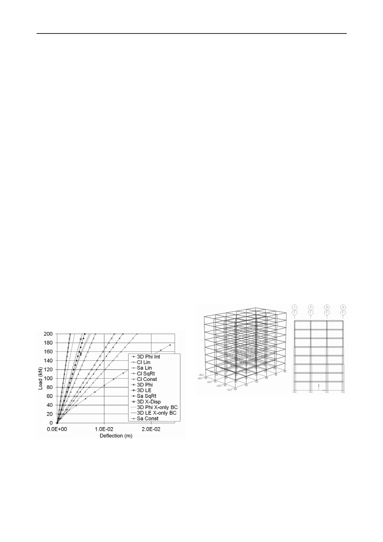
Eurocode 8 suggests formulae for estimating pile stiffness in
seismic response analysis. One should note the effect of soil
profile on behavior, especially for lateral loading. Load
displacement curves based on EC-8 formulae are shown in
Figure 1 for sand (E
s
=20 Mpa) and clay (E
s
=5 Mpa). As one
moves down the legend the responses get stiffer. The lines
marked with Cl or Sa are the clay and sand stiffness based on
linear distribution, square root distribution, or constant with
depth. E
s
values were adjusted so that the average E values for a
12-m pile were equal for the respective distribution profile.
Values for sand and clay are typical for Hungarian soils.
Figure 1. Typical lateral load deflection for Eurocode 8 suggested
spring constants and corresponding FEA results for single piles.
These stiffness values are very high compared to what one
would consider lateral load-deflection behavior for a single pile
in a soil similar to the sand or clay shown. The lines marked 3D
represent 3D FEA of the same pile with different conditions.
The most flexible condition uses an elasto-plastic sand with a
Mohr-Coulomb failure condition and E
s
=20 Mpa,
ϕ
=30 deg
and interface “slip” elements appropriate for the model.
Progressively stiffer responses occur when the interface is
removed, linear elastic (LE) behavior is used, or boundary
restraints are applied. Finally, agreement is reached when the
pile head is restricted to only horizontal displacement and linear
elastic soil is used. Care should be taken when adapting one set
of analysis or field test results for another design approach.
While dynamic conditions may influence the value of
stiffness, other authors have pointed out that the first
approximation to pile stiffness, especially in lower frequency
ranges, is the static displacement profile (Gazetas and Dobry
1984; Blaney et al 1976; Novak and Nogami 1977). Damping
will also reduce response, but to a lesser extent and it primarily
shifts the pile response out of phase with the driving
(earthquake) forces.
3 APPLICATION TO BUILDING DESIGN
The primary focus of research has been to establish more
precisely the effects of SPSI on structural design considerations.
To that end, an example design is used as a basis for study.
3.1
Example Structure
The structure is a 5-bay by 3-bay reinforced concrete frame with
a ground floor, seven floors supported by columns, and a roof
slab. Floor slabs are separated 3.2m c-c and columns are spaced
uniformly 6.0 m c-c. Structural elements were dimensioned
according to EC-2 using factors from the Hungarian National
Annex. While this is a common design, one unique, and
problematic feature of Hungarian designs is the integration of
continuous floor slabs with floor beams. This makes it more
difficult to model beam-column connections and properly
account for stiffness distributions throughout each floor system.
Columns are dimensioned 40x65 cm at the base and taper to
40x40 at the top while beams are uniformly 40x90cm and slab
thicknesses are 20cm. Perspective and profile views are shown
in Figure 2 a, b respectively.
(a)
(b)
Figure 2. Perspective and section view of RC frame. Note elastic
supports added to base of columns.
3.2
Seismic Loading
Hungary is located in a region of moderate seismicity.
Recurrence and intensities of earthquakes have been estimated
by the National Seismological Observatory, Hungarian
Academy of Science. A comprehensive discussion of seismicity
as it applies to engineering design can be found in Tóth et al
(2006). Based on the observatory’s studies, maximum
horizontal accelerations one would expect with 10 percent
probability of exceedance over 50 years are shown in Figure 3.
Design values for seismic loading in EC-8 Annex are presently
being completed; however horizontal accelerations of 0.1-0.15g
can be expected in some areas.


