2837
Technical Committee 212 /
Comité technique 212
translation and rotation (
H
= 5 m and 7 m) as shown in Fig. (4).
Maximum lateral deflection was observed at (0.6 to 0.8
H
) with
the lowest value for small
N
c
. Figure (5) shows normalized
bending moment (
M.d
/
EI
) profiles for different
N
c
values. It is
clear that bending moment increases by increasing
N
c
. The
location of maximum bending moment is at (0.7 to 0.8
H
) with
the lowest value for small
N
c
.
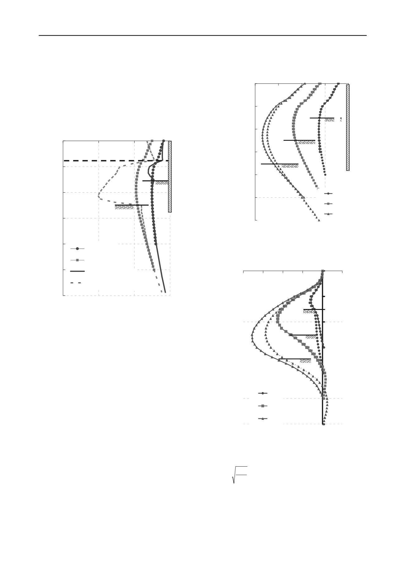
Figure 3. Lateral displacement profile of unsupported and supported
excavation
3.3
Effect of pile wall embedded depth
Figures (4) and (5) show no change in the normalized lateral
pile wall deflection (
U
x
/ d
) and (
M.d
/
EI
), respectively, for
N
c
values of 1.9 and 3.2 and for
D
values of 3 m and 5 m. At
N
c
=
4.5,
U
x
/ d
decreases when
D
increases from 3 m to 5 m. The
same trend can be seen in Fig. (5) for
M.d
/
EI
. For
N
c
= 4.5 (
H
= 7m), the increase of
D
has a significant effect on both lateral
deflection and bending moment of pile wall. By increasing
D
both
U
x
/ d
and
M.d
/
EI
decreases. Figure (6) shows the relation
between
U
x max
/ d
versus
D
. The effect of
D
on the system
stability is clear to be effective in case of
N
c
= 4.5. However, the
increase of
D
more than 7 m (
H/D
= 1) has no contribution to
the system stability.
3.4
Effect of pile diameter and soil-pile stiffness
The Egyptian Code of Practice recommends pile diameter
ranges between 0.3 m and 0.5 m for contiguous pile wall. It is
clear from Figs. (7) and (8) that increasing pile diameter (
d
)
from 0.3 m to 0.4 m decreases both lateral deflection and
bending moment. In Fig. (8),
M
max
.d
/
EI
increases with the
increase of (
H
2
/d.L
o
).
L
o
is soil-pile stiffness factor. The soil-pile
-12
-10
-8
-6
-4
-2
0
0
0.1
0.2
0.3
0.4
Ux/d
Z, (m)
1.9
3.2
4.5
H = 3 m
Pile Wall Side
-12
-10
-8
-6
-4
-2
0
-0.3
-0.2
-0.1
0
Ux, (m)
Figure 4. Lateral displacement profile of contiguous pile wall for
different Nc values (solid line for
D
= 3 m, dashed line for
D
= 5 m)
Figure 5. Normalized bending moment profile of contiguous pile wall
for different
N
c
values (solid line for
D
= 3 m, dashed line for
D
= 5 m)
stiffness can be defined as follows:
4
4
s
o
E
EI
L
(2)
It can be observed from Figs. (7) and (8) that at
N
c
= 4 both
pile wall maximum lateral deflection and maximum bending
moment are not increasing. This means that the pile wall starts
to be more effective at
N
c
= 4 at which the unsupported
excavation fails.
H = 7 m
N
c
H = 5 m
Z, (m)
1.9
3.2
1.9 free
3.2 free
H =
3 m
Pile Wall Side
F.L.
H = 5 m
N
c
Supported
-12
-10
-8
-6
-4
-2
0
-0.5
0
0.5
1
1.5
2
M.d/EI x 10^-3
Z, (m)
M .d/ EI
Supported
unsupported
unsupported
H = 3 m
H = 5 m
H = 7 m
N
c
1.9
3.2
4.5


