 
          2836
        
        
          Proceedings of the 18
        
        
          th
        
        
          International Conference on Soil Mechanics and Geotechnical Engineering, Paris 2013
        
        
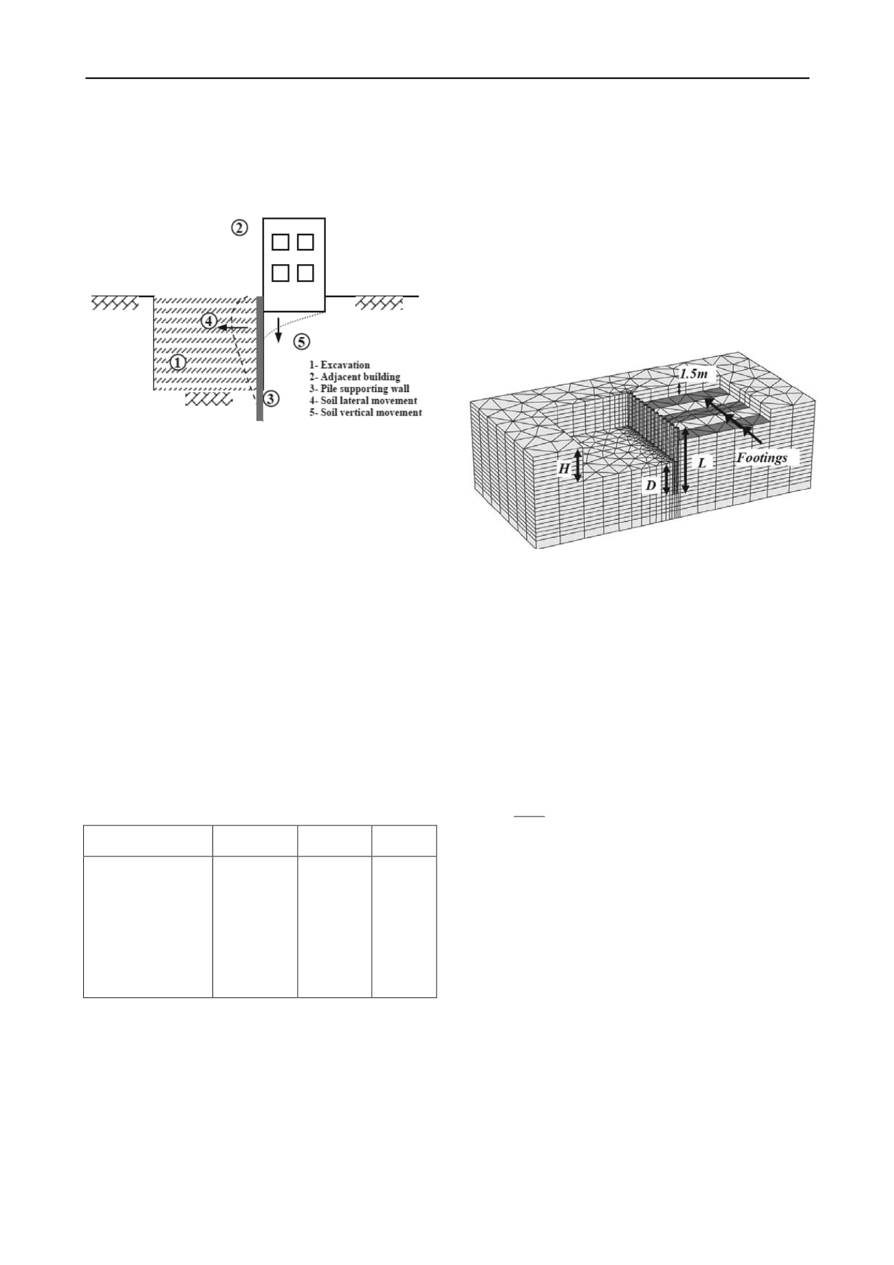
          The foundation level was assumed to be at 1.5 m depth from the
        
        
          ground surface. The mesh was generated as fine mesh at piles
        
        
          where the stresses are expected to be high. Coarse mesh was
        
        
          used at the boundaries of the model where the stresses are low.
        
        
          Figure 1. Problem under study
        
        
          2.2


            Soil modeling


          Soil is assumed to be a deposit of clay. Fifteen node triangular
        
        
          element was used to model the soil. Soil material was assumed
        
        
          to behave as an elastic perfectly plastic material following
        
        
          Mohr-Coulomb model. The soil parameters are presented in
        
        
          Table 1.
        
        
          2.3


            Pile and foundation modeling


          Piles were modeled as a massive circular concrete pile. Pile
        
        
          Young’s modulus (


            E


          ) was 2.1 x 10
        
        
          7
        
        
          kPa. Both pile diameters (


            d


          )
        
        
          of 0.3 m and 0.4 m was considered in the study. They have
        
        
          flexural stiffness (


            EI


          ) of 8350 kN.m
        
        
          2
        
        
          and 26390 kN.m
        
        
          2
        
        
          respectively.
        
        
          The adjacent building foundation is modeled as plate of
        
        
          thickness of 0.5 m. Foundation was idealized with six nodes
        
        
          triangular plate element in the analysis. Interface element was
        
        
          used to represent the contact between plate elements and soil.
        
        
          Table 1. Clay input parameters in FEM
        
        
          Parameter
        
        
          Soft to
        
        
          Medium Clay
        
        
          Medium
        
        
          Clay
        
        
          Unit
        
        
          Dry unit weight,


            γ


          d
        
        
          Wet unit weight,


            γ


          wet
        
        
          Young’s modulus,


            E


            s


          Poisson’s ratio, υ
        
        
          Undrained cohesion, c
        
        
          u
        
        
          Friction angle, φ
        
        
          Dilatancy angle, ψ
        
        
          Interface reduction
        
        
          factor, R
        
        
          18
        
        
          20
        
        
          4000
        
        
          0.3
        
        
          25
        
        
          12
        
        
          0
        
        
          1
        
        
          18
        
        
          20
        
        
          8000
        
        
          0.3
        
        
          50
        
        
          14
        
        
          0
        
        
          1
        
        
          kN/m
        
        
          3
        
        
          kN/m
        
        
          3
        
        
          kN/m
        
        
          2
        
        
          -
        
        
          kN/m
        
        
          2
        
        
          degree
        
        
          degree
        
        
          -------
        
        
          2.4


            Analysis procedure


          The variable parameters used in the analysis are the excavation
        
        
          height (


            H


          ), pile embedded depth (


            D


          ), and pile diameter (


            d


          ) as
        
        
          shown in Fig. (2). Also, both soft to medium clay and medium
        
        
          clay soil were used in the analysis. Pile diameter was assumed
        
        
          to be 0.3 m and 0.4 m with spacing of pile diameter between
        
        
          pile edges.
        
        
          The analysis was carried out in steps. The first step was
        
        
          applying the stress of the adjacent building at the foundation
        
        
          level without the pile wall and the excavation. The second step
        
        
          was activation of the pile wall in the soil. The third step was the
        
        
          excavation of the soil.
        
        
          In the present paper, only bending moment of pile and pile
        
        
          lateral displacement outputs were used in the analysis. All the
        
        
          presented results are of the pile at the middle of the supporting
        
        
          wall. It was found from the results that this pile is the most
        
        
          critical in both lateral deflection and bending moment. The piles
        
        
          at the ends of the wall have the lowest lateral deflection and
        
        
          bending moment profiles. The stress on the foundation level
        
        
          was assumed to be 100 kN/m
        
        
          2
        
        
          . This stress is corresponding to a
        
        
          bearing capacity factor of safety of 2 for the soft to medium clay
        
        
          case.
        
        
          Figure 2. FEM geometry and meshing
        
        
          3 FEM RESULTS AND DISCUSSIONS
        
        
          3.1


            Effect of supporting excavation


          Excavation height (


            H


          ) and cohesion of clay (


            c


            u


          ) are two main
        
        
          parameters in the design of the pile wall. It was found that
        
        
          results should better be related to a factor has both the effect of
        
        
          excavation height (


            H


          ) and undrained soil shear strength (


            c


            u


          ).
        
        
          The stability factor (


            N


            c


          ) joins both


            H


          and


            c


          u
        
        
          parameters in the
        
        
          following relationship as recommended by Polous and Chen
        
        
          (1996):


            u


            c


            c


            H N


          (1)
        
        
          where


            γ


          is the unit weight of the soil.
        
        
          Figure (3) shows lateral displacement profile (


            U


            x


          ) versus
        
        
          depth (


            Z


          ). Both the profile of unsupported soil lateral
        
        
          displacement and pile lateral deflection are shown in Fig. (3).
        
        
          Large soil movement can be observed due to the stress of the
        
        
          adjacent building in the case of unsupported excavation. The
        
        
          lateral displacement increases rapidly as the excavation height
        
        
          increases. Maximum lateral displacement increased from about
        
        
          0.06 m to 0.2 m when


            N


            c


          increased from 1.9 to 3.2. However,
        
        
          the maximum lateral displacement increased to very large value
        
        
          of 1.2 m for


            N


            c


          = 4.5. This means that the excavation is failed at


            N


            c


          = 4.5. When the excavation is supported using contiguous
        
        
          pile wall, soil movement decreases in the zone above the
        
        
          excavation level. However, below the excavation level, there is
        
        
          no obvious decrease in soil movement. It should be noted that in
        
        
          all cases the pile wall is translated horizontally.
        
        
          3.2


            Effect of excavation height


          Pile wall lateral deflection increases as excavation height (


            H


          ) or
        
        
          the stability factor (


            N


            c


          ) increases. As


            N


            c


          increases pile wall
        
        
          movement changes from translation (


            H


          =3 m) to both