2849
Technical Committee 212 /
Comité technique 212
load cell is cylindrical and of stainless steel of the same
diameter as the damper.
4000
3000
2000
3 CASE HISTORY.
This work describes the results of two pseudostatic load tests
performed on large diameter piles buit for a bridge over the
River Calchaquí on the state highway No 37, in the province of
Santa Fe, Argentina. For this bridge were projected sixteen
piles of 1.20 m in diameter and approximately 24 m long with
preload cell. The soil profile of the site is characterized by the
presence of reddish-colored silty clays with interbedded more
greenish layers. The compactness of the soil has significant
horizontally and vertically variations. At the foundation depth
of 24 m the penetration resistance is higher than 50 blows of the
normalized Standard Penetration Test. Ultrasonic cross hole
tests (ASTM D6760) were performed in all the piles on the six
prospecting pipes before and after the load test. The service load
of each pile was designed for 4800 kN and the falling mass was
25 tn. The mass was hanged and dropped using a free fall crane
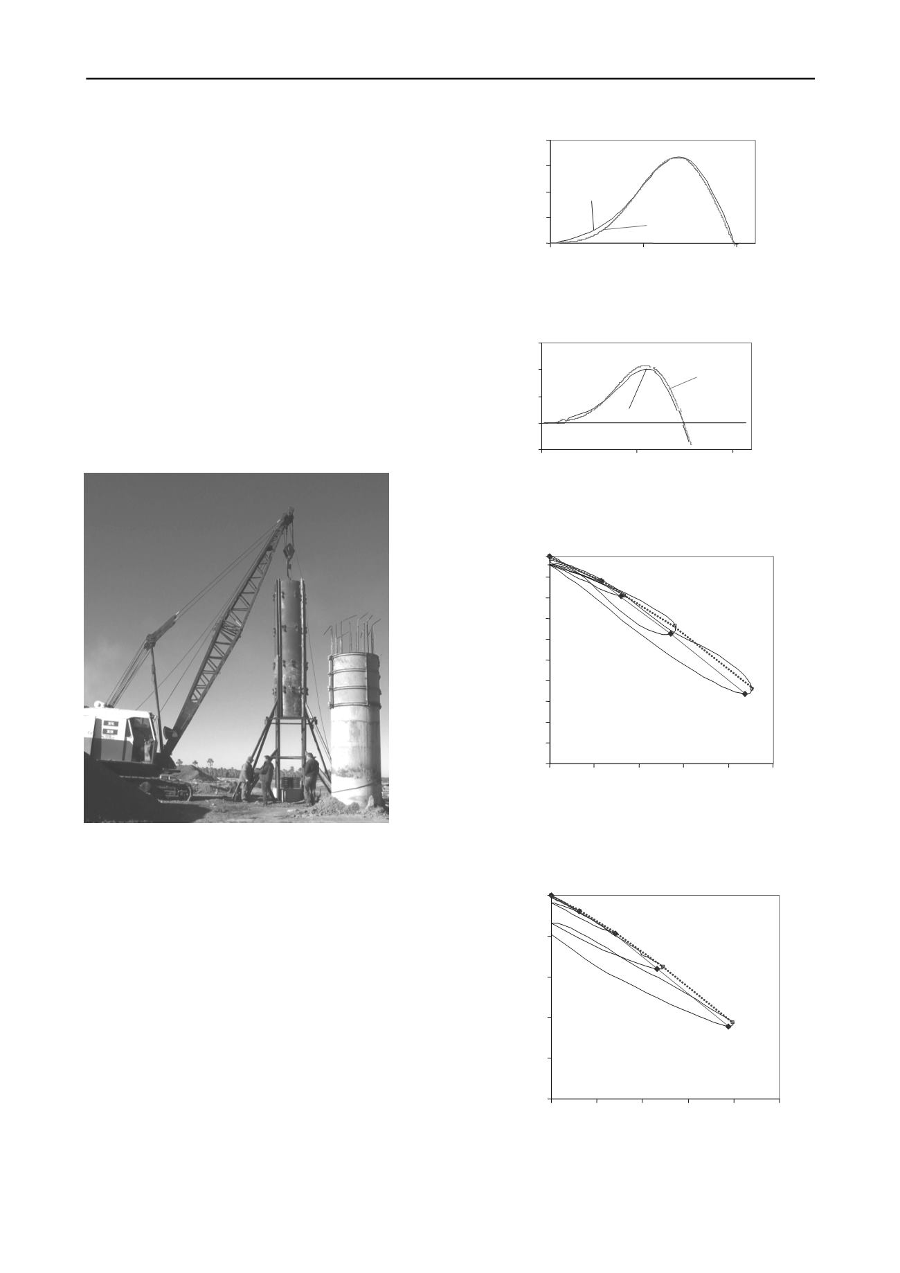
(see Figure 6).
Figure 6. Picuture of one of the piles tested at the site.
Figures 8 to 10 show the typical curves of the recorded force,
velocity and displacement for a single drop of the mass. Note
that loading times exceed the 50 milliseconds which for the
present case can be considered pseudostatic.
Figures 9 and 10 show the curves of load-settlement
obtained for the two piles tested in this work. Notice that in
these figures the results from all mass drops have been included.
The envelope correspond to the total envelop and the corrected
envelop to account for dynamic effect using equation (9) at the
point where the velocity is zero or where the maximum
displacement is attained.
Figure 7. Force function for a falling weight of 25 tn from a drop height
of h=2.2 m
Figure 8. Velocity function for a falling weight of 25 tn from a drop
height of h=2.2 m
Figure 9. Load- settlement envelopes for the pile P2-S tested in this
work. Dotted line corresponds to the total envelop and filled line to the
corrected envelop by removing the dynamic effect.
Figure 10. Load- settlement envelopes for the pile P3-S tested in this
work. Dotted line corresponds to the total envelop and filled line to the
corrected envelop by removing the dynamic effect.
-2.50
-2.00
-1.50
-1.00
-0.50
0.00
4000
Load [kN]
Settlement [mm]
6000
0
8000
2000
10000
-2.00
-1.80
-1.60
-1.40
-1.20
-1.00
-0.80
-0.60
-0.40
-0.20
0.00
0 2000 4000 6000 8000 10000
Load [kN]
Settlement [mm]
-15
-10
-5
0
5
0
50
100
time [mseg]
Velocity [mm/seg]
Measurement
Model
0
1000
Force [KN]
Meassurement
Model
0
50
100
time [mseg]


