2853
Technical Committee 212 /
Comité technique 212
From Fig. 3, it is clear that, the ultimate lateral load (H
u
)
dependent on the slenderness ratio (L/D). A significant
increase on ultimate lateral load with increasing (L/D).
This can be explained by the embedded length, for small
(L/D) is not sufficient to create the full fixation of the
pile. Increasing the inclination of the applied load (α)
will increase the lateral load acting on the pile head.
Therefore, the lateral piles displacement will increase and
decrease the ultimate lateral load.
5.3
Bending moment along the pile length
Figures 4 and 5 presents the experimental bending
moments along the pile length with L/D = 40 in sandy
soil. The strain readings obtained experimentally are
converted to bending moment. In general, the shape of
the diagrams is compatible with the shapes investigated
by Broms, 1964. It is obvious that, the increasing of (α)
increased the maximum values of the bending moment
along the pile length. The maximum bending moment in
case of (α = 90
o
) for pile in soil (A) is about 29 % and 9
% larger than that in case of α = 30
o
and 60
o
respectively.
These percentages are about 13 %, 8 % respectively for
pile in soil (C). From the above mentioned figures, the
bending moment may vanish before the end of the pile.
The depth of the point of the maximum bending moment
increases by increasing the inclination of the applied load
with vertical (α).
It is obvious from the previous figures that, the
maximum bending moments are usually higher for loose
sand than the case of dense sand. Increasing the relative
density of soil decreased the maximum bending moment
along the pile length at the same (α).
5.4
n
h
– deflection relationship
According to Reese and Matlock (1956), the coefficient
of horizontal modulus of sub-grade reaction (n
h
)
is
related to the relative stiffness factor, (T) through the
relation, T =(E
p
I
p
/ n
h
)
1/5
which is used in the analytical
analysis. The value of (T) can be obtained from the
following equation:
y
gs
= y
zg
x H
gs
x T
3
/ E
p
I
p
(Valid for vertical pile only) (2)
where: y
gs
is the lateral deflection of the pile at ground
surface, y
zg
is a non-dimensional coefficient that depends
on the ratio, embedded length / T (for embedded length /
T > 4, y
zg
= 2.435), H
gs
is the
lateral load at ground
surface, E
p
I
p
is the Flexural stiffness of the pile, and (T)
is the relative stiffness.
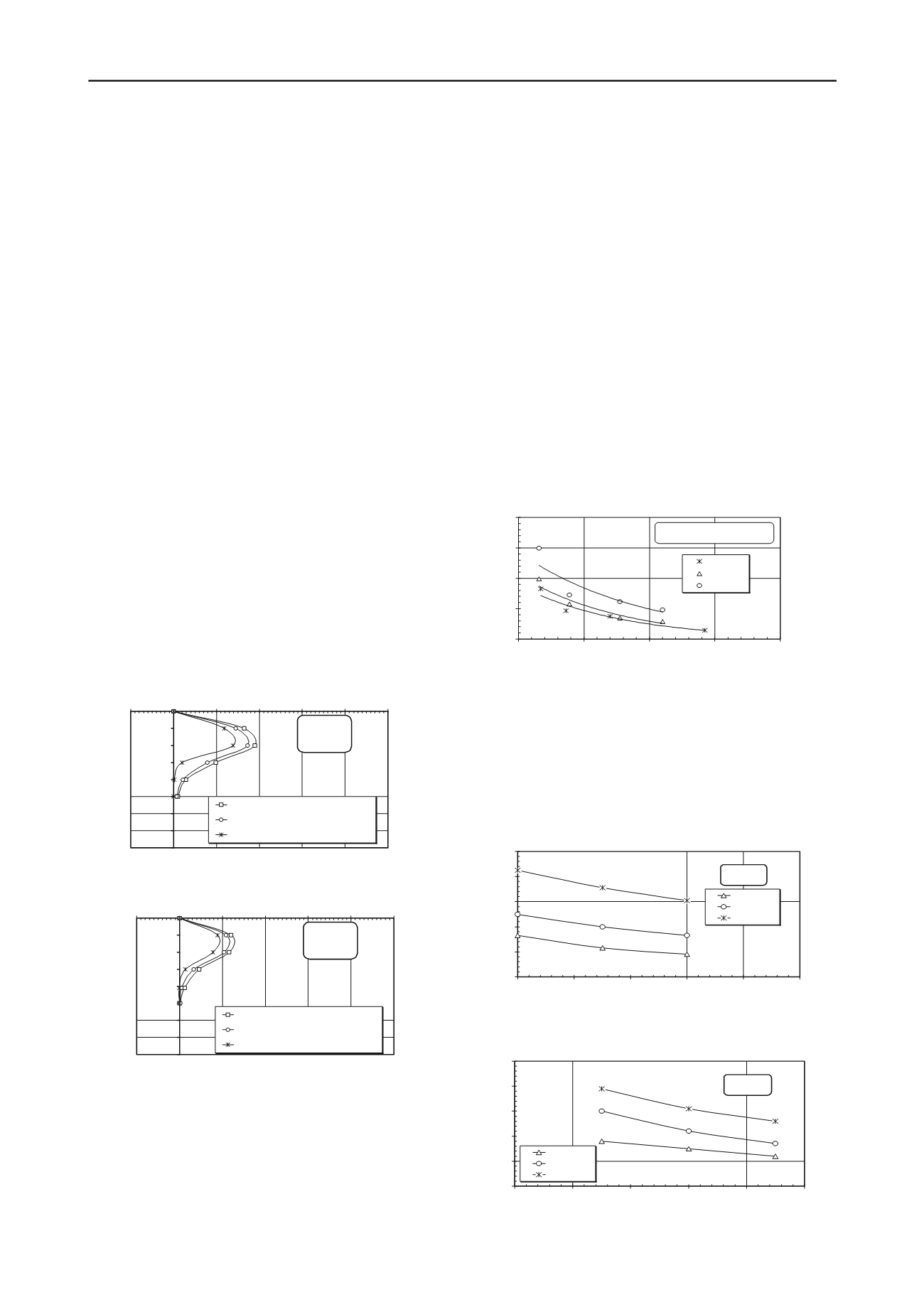
From load – deflection curves and by using the
above equation, the values of (n
h
) were calculated at each
deflection. The results show that the coefficient of
horizontal modulus of sub-grade reaction is significantly
dependent on the deflections at the low load levels and is
relatively insensitive to deflections at high load levels.
Figure 6 shows the coefficient of horizontal modulus of
sub-grade reaction versus deflection in the free head case
for pile with (L/D=40) and inclined load with (α = 30
o
).
From this figure it is clear that the coefficient of
horizontal modulus decreases with the deflection
increase. This conclusion agrees with that drawn by
Alizadeh and Davisson, 1970. It is obvious from that;
relative density of sand has a significant effect on (n
h
)
values.
0.0
1.0
2.0
3.0
4.0
0.0
0.4
0.8
1.2
1.6
Deflection (mm)
n
h
x 10
4
(KN/m
3
)
Dr = 25%
Dr = 45%
Dr = 68%
L/D = 40
Inclined angle of load = 30 degree
Fig. 6: n
h
– deflection relationship for pile under inclined load = 30
o
.
0
5
10
15
20
25
30
35
40
-20
0
20
40
60
80
100
Bending moment x 10
-2
(N.m)
Depth (m x 10
-2
)
Angle of inclined load = 90 degree
Angle of inclined load = 60 degree
Angle of inclined load = 30 degree
L/D = 40
D
r
= 25 %
P = 30 N
5.5
Pile near ground slope
There are many practical situations where piles are
constructed near ground slope. Both axial and lateral
loads were applied to the pile head at ground surface for
pile near ground slope (2H: 1V). The test results from
experimental model are presented. An important
parameter defining the location of the pile head relative
to the crest of the slope (B/D) is considered.
0
20
40
60
80
100
0
20
40
60
80
100
Inclination of applied load (degree)
Ultimate axial load Vu (N)
Fig. 4. Experimental bending moment along the pile length
for soil A.
Fig. 5. Experimental bending moment along the pile length
for soil C.
0
5
10
15
20
25
30
35
40
-20
0
20
40
60
80
100
Bending moment x 10
-2
(N.m)
Depth (m x 10
-2
)
Angle of inclined load = 90 degree
Angle of inclined load = 60 degree
Angle of inclined load = 30 degree
L/D = 40
D
r
= 68 %
P = 30 N
Fig. 7. Relationship between load inclination and (V
u
) for pile at
crest of slope 2H:1V.
B/D = 0.0
L/D = 40
Soil (A)
Soil (B)
Soil (C)
0
10
20
30
40
50
0
20
40
60
80
100
Inclination of applied load (degree)
Ultimate lateral load Hu (N)
B/D = 0.0
L/D = 40
Soil (A)
Soil (B)
Soil (C)
Fig. 8. Relationship between load inclination and (H
u
) for pile at
crest of slope 2H:1V.


