2860
Proceedings of the 18
th
International Conference on Soil Mechanics and Geotechnical Engineering, Paris 2013
2 RESULTS OF PILE TESTS
As has already been discussed above, it was necessary to
erect cast piles of high bearing capacity (2000-3000 ton) within
the bounds of the Moskva-CITY area. These pile tests, con-
ducted by standard technique (load applied from the top), en-
countered technical difficulties and costs, as it was necessary to
install anchor piles, to assemble a load transferring frame and a
system of jacks. Worldwide such pile tests, Moskva-CITY sky-
scrapers inclusive, are done as per the Osterberg method, using-
submersible jacks. The jacks were installed in the pile body, the
tested pile (its upper part) serving as their stop.
Within the Moskva-CITY area in order to determine side and
tip resistances in particular soil layers there were installed gaug-
es in the piles to measure relative deformations of the pile shaft
and forces in reinforcement. Stresses were determined, using the
elastic modulus values of concrete
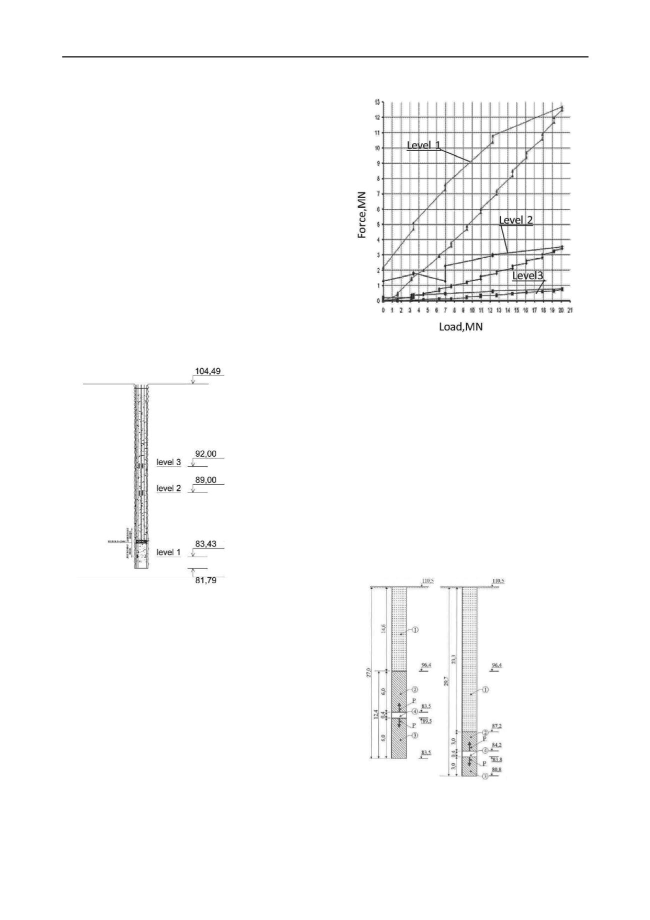
Figure 3 shows the 1,2 m diam. 22,6 m long test pile TP1 lon-
gitudinal section on site 11 with jacks locations shown (eleva-
tion 84,93) and gauges at three elevations (1…3) bottom-up:
84,43 m (1.5 m below jacks); 89,0 and 92,0 m (4 and 7 m above
jacks).
The test showed that for maximum load 20,1МN, the jack up-
per plate dis-
placement was
1,7 mm, that of
the lower one 2,3
mm, the forces at
level 1 were 12,5
МN
(elevation
84,43 m); at level
2 – 3,4 МN (ele-
vation 89,0 m)
and at level 3 –
0,8 МN (eleva-
tion 92,0 m).
Figure 3. Cross section schematic of TP1 test pile (site 11)
Evidently, internal forces in the pile decrease fast to less than
5% at 7 m distance from the jacks (Figure 4). This shows high
values of strength and deformation parameters of the soil.
The obtained distribution of forces in the pile body yielded the
pile design side resistance F
i
:
F
i
= (N
0
– N
i
)/A
i,
(1),
with F
i
as pile design side resistance over area A
i
between
two levels of sensors i and jacks 0;
N
0
and N
i
as forces in jacks and in piles at the level of sen-
sor i respectively.
The analysis, based on equation 1, yielded design side resis-
tance for 1…3 to be F1= 1,34МПа; F2= 1,1МПа; F3=0,73МПа.
The difference of the analytical values is due to difference of
design resistances mobilization rates at different levels, depend-
ing on pile versus soil displacements, as well as to certain pecu-
liarities of the surrounding soil properties.
Similarly equation 1 gave measured values of side resistance
over other segments, that were obtained on other sites. The
values were within 12-20 MN (Table 1), mainly 18 – 20MN.
The causes of this scatter are similar to those mentioned above
for test pile ТР1.
Figure 4. The distribution of forces in the body of the pile.
Force
At sites 12 and 13 there were staged special tests to establish
pile side resistances. A 10,5 m long 1,2 m diam. pile fragment
was tested at site 12 with the help of jacks, installed at 4 m dis-
tance from the pile fragment top (elevation 81,6 m).For maxi-
mum 33,30 MN load the fragment settlement was 3,2 mm. The
calculated pile side resistance was F = 2,55 MN/m
2
.
Similar tests of two 1.5 m diam. pile fragments 6 m long
(item 2,3, Figure 5а) and3 m long (item 2,3, Figure 5b) were
done at site 13 (
Zaretsky Yu.K., Karabajev M.I. 2006; Duzceer R
. et
al, 2009).
The fragments were cast at 14,6 m and 23,3 m depths from
the ground surface (Figure 4). The boreholes above the frag-
ments were filled with rubble. The test side resistances of the
pile fragments were F = 2,00 – 2,20 MN/m2. Therein, the 3 m
long fragment 2 (Table 1, pile 13c, Figure 5b) displaced 17 mm
(i.e. ultimate side resistance was mobilized) F = 2,20
MN/м2.The 6 m long fragment 2 (Table 1, pile 13а, Fig.5а) –
2,00 MN/m2. Other results are given in Table 1.
a)
b)
Figure 5. Pile cross section and test set-up on site 13
Pile test data yielded high ultimate side resistance F = 2,20 –
2,55 MN/m2.
To prove that the above design solutions are valid and safe
there was developed a special set-up on site 16 (Figure 6) and a
procedure for cast piles static tests by 36 MN vertical static load.


