 
          2861
        
        
          Technical Committee 212 /


            Comité technique 212


          Table 1. Result of pile test.
        
        
          Pile parameters
        
        
          Site
        
        
          (Pile)
        
        
          Ø, m
        
        
          L, m
        
        
          Head
        
        
          level, m
        
        
          Jack
        
        
          level, m
        
        
          Max
        
        
          load, MN
        
        
          Max
        
        
          displacement
        
        
          head/tip, mm
        
        
          Side resistance determination
        
        
          method
        
        
          Pile side
        
        
          resistance
        
        
          MN/m
        
        
          2
        
        
          3(1)
        
        
          1,2
        
        
          28
        
        
          113
        
        
          86,1
        
        
          20
        
        
          3,1/1,5
        
        
          D
        
        
          1,20
        
        
          3(2)
        
        
          1,2
        
        
          28
        
        
          113
        
        
          86,1
        
        
          20
        
        
          1,8/2,5
        
        
          D
        
        
          1,20
        
        
          4(1)
        
        
          1,2
        
        
          28,6
        
        
          110,4
        
        
          87,4
        
        
          26,5
        
        
          4,1/1,7
        
        
          D
        
        
          -
        
        
          4(2)
        
        
          1,2
        
        
          28,0
        
        
          110,4
        
        
          84,4
        
        
          24,5
        
        
          3,4/1,4
        
        
          D
        
        
          -
        
        
          11(1)
        
        
          1,2
        
        
          22,6
        
        
          104,5
        
        
          85
        
        
          20,00
        
        
          1,8/2,1
        
        
          D
        
        
          1,30
        
        
          11(2)
        
        
          1,2
        
        
          22,6
        
        
          104,5
        
        
          85
        
        
          16,50
        
        
          1,0/1,5
        
        
          D
        
        
          1,80
        
        
          12
        
        
          1,5
        
        
          10,5
        
        
          85,1
        
        
          81,6
        
        
          33,30
        
        
          3,2/7,5
        
        
          D,F( 4)
        
        
          2,55 (1,55)*
        
        
          13А
        
        
          1,2
        
        
          27
        
        
          109
        
        
          89
        
        
          33,3
        
        
          6,1/3
        
        
          F(6)
        
        
          2,00
        
        
          13Б
        
        
          1,2
        
        
          29,7
        
        
          109
        
        
          83,7
        
        
          25,13
        
        
          17/6
        
        
          F(3)
        
        
          2,20
        
        
          14 (1)
        
        
          1,5
        
        
          19,2
        
        
          103,2
        
        
          88,4
        
        
          33,33
        
        
          8/65
        
        
          D
        
        
          2,00
        
        
          14 (2)
        
        
          1,5
        
        
          19,2
        
        
          103,2
        
        
          92,6
        
        
          33,33
        
        
          16/4
        
        
          D
        
        
          1,90
        
        
          15 (1)
        
        
          1,5
        
        
          20,4
        
        
          103,8
        
        
          93,4
        
        
          1350
        
        
          4/150
        
        
          D
        
        
          200
        
        
          15 (2)
        
        
          1,5
        
        
          19,4
        
        
          103,8
        
        
          86,4
        
        
          3333
        
        
          10/10
        
        
          D
        
        
          200
        
        
          16(1)
        
        
          1,5
        
        
          24,3
        
        
          118,5
        
        
          114
        
        
          3000
        
        
          8,3**
        
        
          F(19)
        
        
          33
        
        
          16(2)
        
        
          1,5
        
        
          24,3
        
        
          118,5
        
        
          114
        
        
          3200
        
        
          7,2**
        
        
          F(19)
        
        
          36
        
        
          *2,55(1,55) – values with no brackets were  determined  from  tensometer data analysis , in brackets from fragment test data;** top-down fragments
        
        
          tests ; D, F – side resistance was determined as per equation 1 and from pile fragment  test data ; F(4) – fragment length m.
        
        
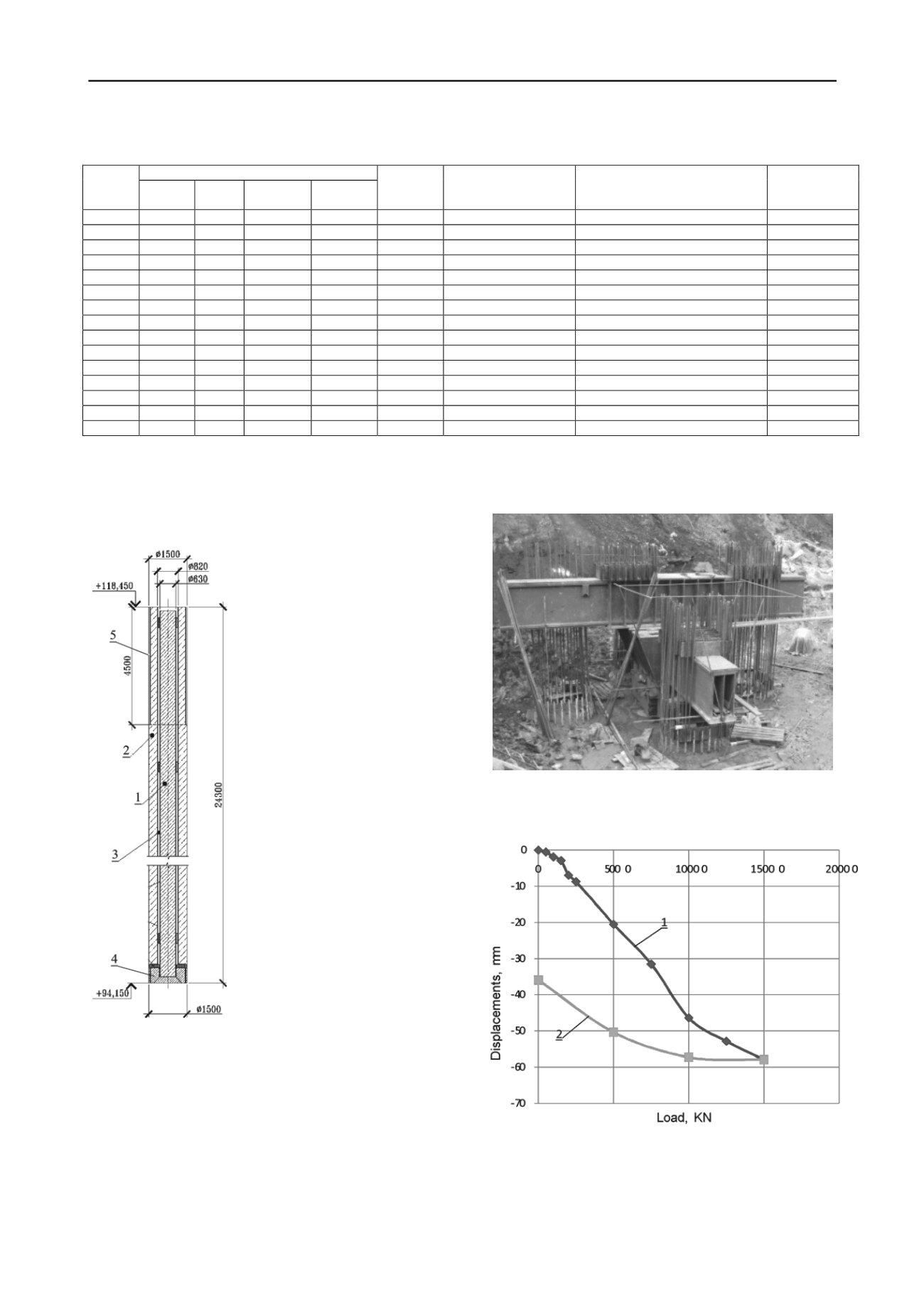
          In order to separate side and tip resistances the pile consisted
        
        
          of two parts: inside part 1 (630 mm external diam.) and outer
        
        
          part 2 (1500 and 820 mm ring diam.).  The hollow space be-
        
        
          tween the pile segments (3) was filled with elastic material to let
        
        
          the parts to freely slide against each
        
        
          other. The interior part (1) was
        
        
          connected with a stiff plate (4). In
        
        
          order to isolate the pile exterior top
        
        
          (2) from the soil mass an external
        
        
          casing tube was installed on the top
        
        
          (5). The loaded system included
        
        
          two steel box cross beams (Figure
        
        
          7), connected with service piles,
        
        
          used as anchors.
        
        
          The tests were started by load
        
        
          application to the interior part of the
        
        
          pile (1) and through it to the plate
        
        
          (4) (pile tip test).
        
        
          Then the set-up was adjusted to
        
        
          step wise load application to the
        
        
          exterior part of the pile (2), and pile
        
        
          side resistance was determined.
        
        
          Figure 7. Loading set-up
        
        
          The initial plate test and elastic
        
        
          spacers between pile parts prevent
        
        
          data distortion in the pile exterior
        
        
          side test.
        
        
          The test results (Figure 8,9)
        
        
          show that the central part of the
        
        
          plate displacement largely exceeds
        
        
          that of the pile-shell.
        
        
          Figure 6. Loading set-up
        
        
          The pile tip resistance for equal displacements was one or-
        
        
          der of magnitude less than that of the side resistance and several
        
        
          orders of magnitudes less than the analytical value. This fact
        
        
          shows presence of mud on the borehole bottom, which could not
        
        
          be removed during drilling operations.
        
        
          Soil resistance below pile tip at other sites demonstrated its
        
        
          strong dependence on the quality of the bottom face and on the
        
        
          quality of special operations (soil grouting), e.g. on site 4 grout-
        
        
          ing was done to 5 m below the pile tip.
        
        
          1 –   loading, 2 -   unloading
        
        
          This shows the necessity for extra operations to clean and to
        
        
          compact the bottom, e.g. by grouting the soil under pile tip, by
        
        
          compacting the bottom, e.g. by ramming broken stone or stiff
        
        
          concrete into the bottom, etc. (Petrukhin et al, 2011).
        
        
          Figure. 8. Pile   tip   test diagram