2764
Proceedings of the 18
th
International Conference on Soil Mechanics and Geotechnical Engineering, Paris 2013
(a) Modeling of a piled raft
(b) Flowchart
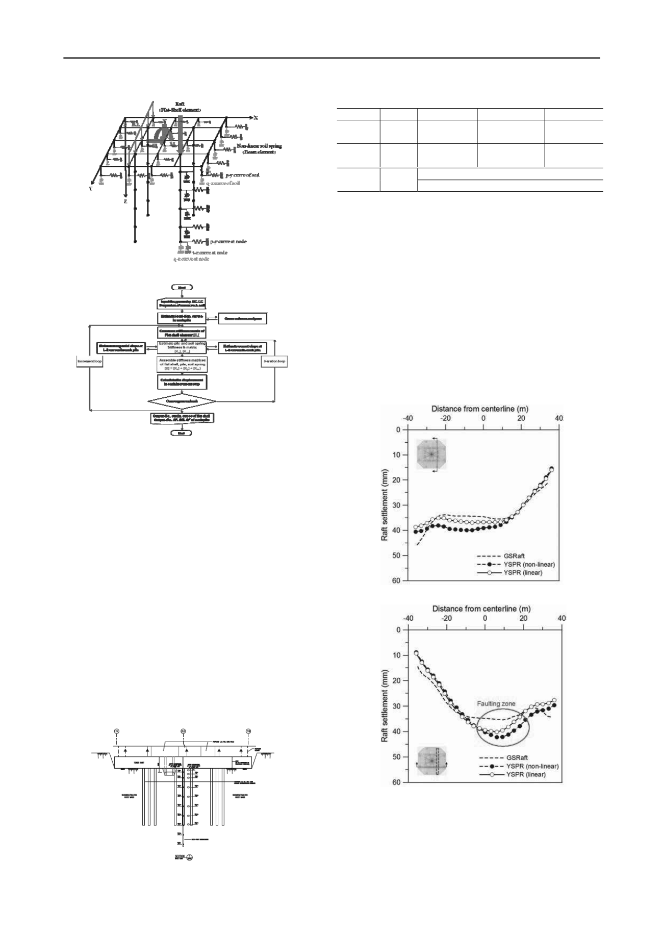
Figure 1. YSPR(Yonsei Piled Raft)
2.2 Comparison with case history
The validity of the proposed method was tested by comparing
the results from the present approach with some of the case
history.
As shown in Fig. 2, preliminary design case of piled raft
(OO super tower) conducted at high-rise building construction
sites in Korea were representatively selected for the design
application. The construction site is comprised mainly of
normally banded gneiss, brecciated gneiss and fault core zones.
Based on the results of pressure meter, Goodman Jack and plate
load tests carried out in the field, a non-linear elastic modulus
design line is established to represent the stiffness of the ground.
A schematic diagram of a raft foundation with piles is shown
in Fig. 2. This structure consists of a raft, and 112 of ground
strengthen piles. The piles have an embedded length of 30 m, a
diameter of 1.0 m. A large raft size 71.7x71.7m with a thickness
of 6.0 m is resting on a banded gneiss. The raft and ground
strengthen piles, with a Young’s modulus of 30GPa and 28GPa
respectively, is subjected to a vertical load (P
total
=6,701MN).
Table 1 summarizes the material properties used in the case
studies.
Figure 2. Preliminary design case
Table 1. Material propertiess
Type
Depth(m)
E (MPa)
ν
Pile
Concr
ete
0~-30
28,000
0.2
Raft
Concr
ete
0~6.0
33,234
0.15
Soil spring stiffness (kPa/m)
Soil
Gneiss
0~204,250
Fig. 3(a) and (b) shows the raft settlement at different section
predicted by GSRaft and YSPR. Agreement between the
GSRaft and YSPR of settlement is generally good; however
there is a slight difference in prediction of settlement in the
faulting zone which the sudden drop of the magnitudes were
occurred. This can be attributed to the appropriate assumption
of material properties due to no accurate ground investigation
data on this section. As shown in this result, the prediction by
the proposed method has a considerably larger settlement than
the settlement calculated by the existing solution. This is
because the existing method ignores lateral displacement due to
membrane action of flexible raft and, thus, overestimates the
lateral stiffness of raft and small displacement in raft lateral
behavior. Although there are no measured profiles of raft
settlement, the proposed analysis method showed reasonably
good correspondence with well-known in-house program.
(a) Section1
(b) Section2
Figure 3. Raft settlement distribution
3 INTERACTIVE ANALYSIS OF SUPER- AND SUB-
STRUCTURE
3.1 General
The unified analysis of piled foundation in long span bridges
and buildings has become an important issue in structure


