 
          2761
        
        
          Technical Committee 212 /


            Comité technique 212


          2.3


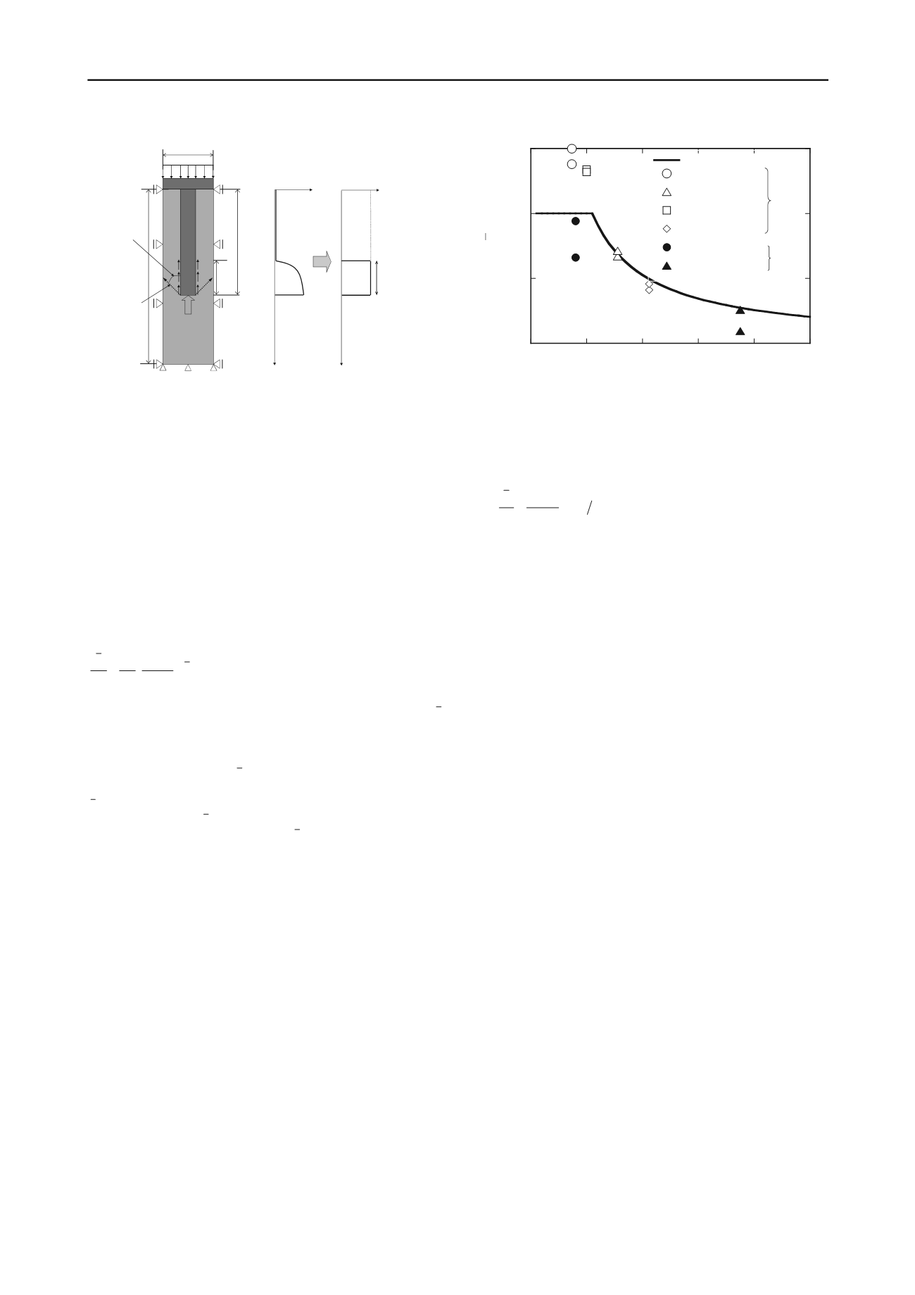
            Prediction model for skin friction of floating-type column


          In this study, in order to evaluate the skin friction applied
        
        
          around the surface of floating-type columns, FEM analysis with
        
        
          the Cam-clay model as the constitutive equation was performed
        
        
          using axi-symmetric and plane strain models (Ishikura et al.,
        
        
          2006).


            H


          ,


            H


          1
        
        
          and


            L


          denote the ground depth, the improvement
        
        
          depth and the distance between the improved columns or walls,
        
        
          respectively. The ground surface was deformed equally by the
        
        
          rigid plate on the assumption of shallow stabilized ground.
        
        
          From the results of FEM analysis, the upward skin friction
        
        
          applied around the surface of the improved column is
        
        
          determined using the approximate formula given in Eq. (1).


            LH p


            c


            p


            u


          /
        
        
          1
        
        
          1 0 0
        
        
          ·


          (


          �
        
        
          )
        
        
          (1)


            u


            c


            p


          0
        
        
          denotes the pre-consolidation pressure of the soft clay.


          denotes the averaged skin friction applied around the surface of
        
        
          the column. This value is obtained from the difference between
        
        
          the stress applied on and immediately below the improved
        
        
          column. Each value of


          is normalized by the


            p


          0
        
        
          .


            H


          1
        
        
          is
        
        
          normalized by the value of


            L


          .  The normalized average friction
        
        
          0/


            p


          decreases with an increase in


            H


          1
        
        
          /


            L


          . Furthermore, the
        
        
          maximum value of
        
        
          0 /


            p


          is almost equal to the shear strength
        
        
          ratio
        
        
          0
        
        
          . It is clarified that
        
        
          /


            p uc


          changes under several
        
        
          conditions with different values of


            H


          ,


            H


          1
        
        
          , and


            L


          .
        
        
          Here,


            u


          is the undrained shear strength. The approximate
        
        
          curve almost corresponds to the relationship between the
        
        
          upward averaged skin friction and the improvement parameters.


            c


          It is considered that skin friction is mobilized around surface
        
        
          acting relative displacement between the column and soft clay.
        
        
          The combined foundation transfers the load to the pile group via
        
        
          the raft; hence soft clay between the friction piles in the upper
        
        
          part of the combined foundation is enclosed.
        
        
          Figure 6 shows the hypothesis of skin friction around the
        
        
          surface of columns. As shown in this figure, if the slip surface
        
        
          that has inclination of 45 degrees from the pile end to the upper
        
        
          part has occurred, the intersection adjacent the column has been
        
        
          existed. When the length from this intersection to the column
        
        
          end is supposed the length that the skin friction is mobilized, the
        
        
          equivalent conversion ratio


          which is defined as the ratio
        
        
          between the column length and the length that the skin friction
        
        
          is mobilized is introduced in Eq.(2).
        
        
          (2)
        
        
          1
        
        
          /


            HL


          When


            u


          is defined as the undrained shear strength near the
        
        
          surface acting relative displacement between the column and
        
        
          soft clay,


            c


          is also given in Eq.(3) by using Eq.(1).
        
        
          0
        
        
          0.5
        
        
          1
        
        
          1.5
        
        
          0
        
        
          1
        
        
          2
        
        
          3
        
        
          4
        
        
          5
        
        
          Approximated formula


            H


          1
        
        
          /


            H


          = 0.55, 1pile


            H


          1
        
        
          /


            H


          = 0.55, 5piles


            H


          1
        
        
          /


            H


          = 0.75, 1pile


            H


          1
        
        
          /


            H


          = 0.75, 5piles


            H


          d1
        
        
          /


            H


          = 0.74, 1pile


            H


          1
        
        
          /


            H


          = 0.74, 3piles
        
        
          α
        
        
          =
        
        
          τ
        
        
          /


            c


          u


            H


          1
        
        
          /


            L


          Group
        
        
          column
        
        
          Wall
        
        
          45
        
        
          °
        
        
          +Φ/2
        
        
          Slip
        
        
          surface


            L


            H


          1


            αH


          1
        
        
          Skin friction
        
        
          τ
        
        
          Skin friction
        
        
          τ


            H


          1
        
        
          Modeling


            c


          u


            αH


          1


            H


          Depth
        
        
          Depth
        
        
          Figure6. Hypothesis of skin friction around the surface
        
        
          Figure7. Formulation of equivalent conversion ratio


            α


            LH c


            u


          /
        
        
          1
        
        
          1


          (


            LH


          1
        
        
          �
        
        
          1)
        
        
          (3)
        
        
          Figure7 shows the formulation of the equivalent conversion
        
        
          ratio


          . Experimental values of two types of loading model
        
        
          tests were also plotted (group column type and wall type). As
        
        
          shown in this figure, equivalent conversion ratio


          nearly
        
        
          corresponds with the calculated value from Eq.(2) or Eq. (3).
        
        
          3
        
        
          TENDENCY OF SKIN FRICTION MOBILIZATION IN
        
        
          THE  CONSOLIDATION PROCESS
        
        
          3.1


            Numerical modeling


          In this section, in order to evaluate skin friction mobilization of
        
        
          this type of improved ground during consolidation, time
        
        
          dependent behaviors of skin friction were investigated by using
        
        
          FEM analysis. Numerical analysis has already been performed
        
        
          to investigate the neutral plane of pile in the consolidating
        
        
          ground (Yan, W. M. et al., 2012). Figure 8 shows the Axi-
        
        
          symmetric model for evaluating skin friction in this study.
        
        
          Elastic model was applied to the shallow stabilized ground
        
        
          (raft) and column (pile). Modified Cam-clay model was also
        
        
          used in the soft clay as the constitutive equation. In this figure,


            h


          means the thickness of shallow stabilized ground,


            H


          1
        
        
          and


            L


          means the column length and distance between columns.


            H


          and


            d


          also means the thickness of soft soil layer and column
        
        
          diameter. In this analysis, in reference to the field measurement
        
        
          (Ishikura et al., 2009),


            h


          ,


            H


          1
        
        
          ,


            d


          ,


            L


          was set to 1.0m, 6.5m, 1.0m,
        
        
          2.0 m , respectively. Table1 shows the material parameters. The
        
        
          ground water level was located at the ground surface of model
        
        
          ground and drainage boundaries were set to the upper and lower
        
        
          part of model ground. After applying to the 1 kPa on the ground
        
        
          surface, 150 kPa of


            Δp


          was applied to the ground surface in the
        
        
          assumption of fill with 7.5m. In this study, full shear resistance
        
        
          of soil-pile interface was modeled by Eq.(4).
        
        
          '
        
        
          '
        
        
          tan


            n


            f


            R Rc


          (4)
        
        
          Here,


            c


            ’


          and means the effective cohesion and friction angle
        
        
          of soil,


            n


          means the normal effective stress applied to the
        
        
          interface and


            R


          means the interface friction coefficient. These


            R


          values were used in 0.90, 0.75, 0.50, 0.30, respectively.
        
        
          '