2756
Proceedings of the 18
th
International Conference on Soil Mechanics and Geotechnical Engineering, Paris 2013
Research on the Load-Bearing Behaviour of Bored Piles with Different Enlarged Bases
18
th
International Conference on Soil Mechanics and Geotechnical Engineering, Paris 2013
2
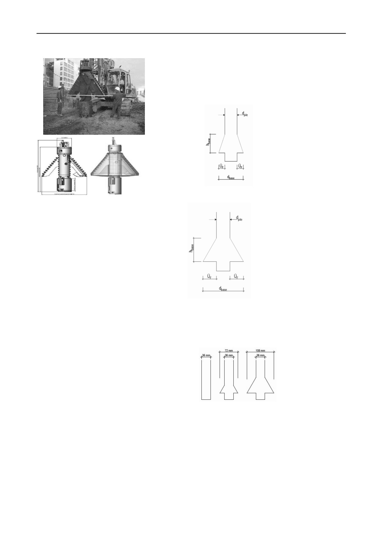
Figure 2. Belling bucket Bauer
This aforesaid drilling tool is denoted as a pile base extension
cutter and generally consists of two cutting arms and a cutting
body that functions as a borehole reamer to produce a pile (an
under-pile) beneath the pile base enlargement.
2.2
Advantages of the Pile Base Enlargement
• Higher load-carrying capacity of the single pile or
settlement reduction
• Fewer piles under concentrated loads
• Simple pile head construction (none or smaller pile head
slabs)
• Reduced pile shaft diameter with shallower drilling
depths
• Smaller drilling equipment (more favorable BE/BR,
lower costs)
• Savings on pile concrete (more favorable relationship
load/m
3
concrete)
2.3
Pile geometry
2.3.1
Pile Shaft
The drilled pile shaft exhibits a constant cross section, which is
selected according to the static requirements for the internal bearing
capacity from the top of the pile down to the beginning of the
enlargement. Usually the pile is manufactured using a C30/35
concrete. Unreinforced or partially reinforced piles are permissible
in principle, while at the same time the load distribution according
to EC 2 must be considered. With wide base enlargements and high
pile loadings, high-strength concrete can be used, permitted in
accordance with DIN EN 1536, or steel fiber reinforcing would be
useful.
2.3.2
Pile base
It must be noted foremost, that the widening of the foot of the
pile is dependent on the basic geometry of the drilled pile, meaning
the diameter of the shaft and the overboring equipment used. This is
due to the different opening mechanisms of the cutting arms.
Modern cutters, like those presented in the current paper, are able to
produce flat bottoms within the area of the widening, which was not
the case with older models. Also with these types of devices,
depending on the manufacturer, an under-pile beneath the
enlargement with the same diameter as the shaft is created. This has
a positive influence on the friction of the base of the overboring to
provide additional support and provides a stopper effect which
mechanically increases the bottom of the pile. Investigations by
BAUER showed that with these new type cutting devices, even the
largest, all pile foot enlargements according to DIN EN 1536 can be
manufactured in the soils envisioned for special foundation
construction safer and with a higher quality.
According to DIN EN 1536 the area of the foot enlargement is
reduced as follows depending of the soil in the base area:
with cohesionless soils (See Figure 3):
a)Foot height / Foot Overboring = h
Base
/ Ü
F
≥ 3 (similar to DIN
4014)
b)
max. permissible pile foot diameter = 2 x pile shaft
diameter, d
Base
Figure 3. Pile foot base enlargement in
cohesionless soils
In cohesive soils (See Figure 4):
a)Foot height / Foot Enlargement = h
Base
/ Ü
F
≥ 1.5
b)max. allowable pile foot diameter = 3
x pile shaft diameter, d
Base
(1.5 fold
value from DIN 4014)
c)max. allowable pile foot area = 10 m²
max. allowable pile foot diameter =
3.57 m
Figure 4. Pile foot base enlargement in
cohesive soils
2.4
Pile tests
2.4.1
Pile tests Description
The investigation of the differences in the bearing capacities of the
piles depending on the different pile foot base enlargements (see
Tinteler, Herrmann) was carried out with load tests on scale models.
(see figure 5).
Figure 5. Cross section of the pile models (M = 1:25)
In each case two tests conditions were investigated: using a
casing in order to eliminate skin friction and to measure point
resistance R
b
only, and without a casing to determine the entire pile
resistance R
b+s
. The experimental soil was a sand with a uniformity
coefficient, U, of 2.5 – 2.8. It can further be said that this soil was
prepared by an in-place compaction, I
D
, of approximately 0.74,
which corresponds to a dense condition.
For statistical reasons and to acquire meaningful strong results,
for each case three identical loads (in each case three per cross
section with and without casing – altogether 18 trials) were applied
with the different models (See Figures 1 & 5).


