2750
Proceedings of the 18
th
International Conference on Soil Mechanics and Geotechnical Engineering, Paris 2013
The unified pile design approach is the combination of capacity,
drag load, settlement, and downdrag. The main tenet of method
includes the sustained working load, the shaft resistance
distribution, and the soil settlement distribution; they interact
with the neutral plane location, the downdrag, and the pile toe
load-movement response.
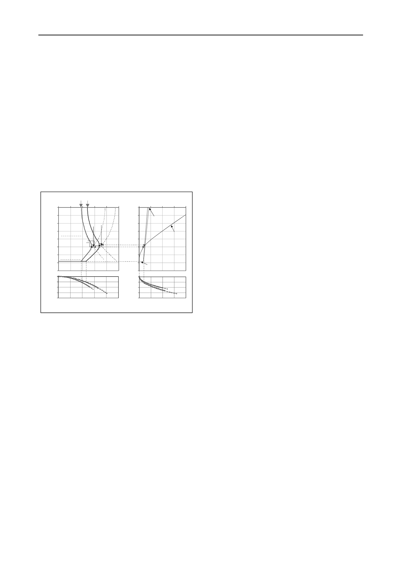
The back-analysis of two tested piles is performed by the
software UniPile (Goudreault and Fellenius 1999) and the
results are presented in Figure 10. Figure 11 shows the long-
term load distribution in the piles TP01 and TP02 starting from
the 3.8 and 4.8 MN sustained load from the structure,
respectively. Assuming that the drag loads accumulated from
negative skin friction are fully mobilized, the maximum loads in
the piles are about 5.8 and 7.2 MN at the neutral planes at 23
through 25 m depth below the ground surface. The maximum
loads are well within the axial structural strength of both piles.
The settlements at the neutral planes and the 'elastic' shortenings
of the piles are about 11 through 13 mm and 9 through 11 mm,
respectively.
The evaluated pile Young’s modulus, E, for the piles TP01
and TP02 correlated to 25 and 22 GPa for the nominal pile cross
section of both piles. The shaft resistances were small and
correlated to an effective stress analysis beta-coefficient of 0.2
and 0.3. The shaft resistances between O-cell and SG1 were
strain-softening. It appears that the shaft resistances for both test
piles were affected by presence of slurry filter cake between the
concrete and the soil.
The measured pile toe stress-movements in percent of
nominal diameters for the piles were essentially linear trend and
have shown no tendency toward an ultimate resistance. The pile
toe response was very soft and not representative for a pile in
high weathered sandstone.
Back-analysis by the Unified Design method shows that the
structure maximum long-term settlements of the piles will be
about 20 mm, which is well below the acceptance value of
40 mm assigned to the project.
6 REFERENCES
0
5
10
15
20
25
30
35
40
0 2 4 6 8 10
DEPTH (m)
Thousands
Silty Sand
TP01
FirmClay
High Weathered Sandstone
Neutral Planes
LOAD (MN)
Max. Load
in Piles
TP02
0
25
50
75
100
0 2 4 6 8 10
Pile Toe Load - Movement
LOAD (MN)
TP02
TP01
0
5
10
15
20
25
30
35
40
0 25 50 75 100
DEPTH (m)
SETTLEMENT (mm)
TP02
Typical Soil
Settlement
Toe
Penetrations
TP01
Neutral Planes
Settlement of
pile heads
0.0
2.5
5.0
7.5
10.0
0 25 50 75 100
MOVEMENT (mm)
Pile Toe Load -
Movement
TP02
TP01
MOVEMENT (mm)
LOAD (MN)
Da Nang University of Technology, 2008. Reports on Bored Pile
Testing for SeaBank Tower, Da Nang, Vietnam, 54p.
Fellenius, B.H., 1984.
Negative skin friction and settlement of piles
.
Proceedings of the Second International Seminar, Pile Foundations,
Nanyang Technological Institute, Singapore, 18 p.
Fellenius, B.H., 1988. Unified design of piles and pile groups.
Transportation Research Board, Washington, TRB Record 1169,
pp. 75-82.
Fellenius, B.H., 1989. Tangent modulus of piles determined from strain
data.
ASCE, Geotechnical Engineering Division
, the 1989
Foundation Congress, F.H. Kulhawy, Editor, Vol. 1, pp. 500-510.
Fellenius, B.H., 2011. Basics of foundation design, a text book.
Revised Electronic Edition,
], 374 p.
Fellenius B.H. and Nguyen H.M., 2013. Large Diameter Long Bored
Piles in the Mekong Delta.
International Journal of
Geoengineering Case Histories,
2(3), 196-207.
Goudreault, P.A. and Fellenius, B.H., 1999. UniPile Version 4.0 for
Windows.
Users
Manual,
UniSoft
Ltd.,
Ottawa,
] 64 p.
Figure 11. Long-term load distribution and settlement profile
for working piles with same diameter and length as the two test
piles.
Nguyen H.M., 2013.
Analysis of Bidirectional Test for Red River
Bridge, Vietnam.
The 3th International Conference on Geotechnical
Engineering, Hammamet, Tunisia, 9p.
As indicated in Figure 1, the soil at depths of the neutral
planes is compressible; this can cause an increase of the pile
penetration into the highly weathered sandstone, i.e., downdrag.
However, this would partially be offset by the increase of the
pile toe force with a subsequent lowering of the neutral plane.
Osterberg, J.O., 1989.
A new device for load testing driven piles and
drilled shafts separates friction and end bearing
. Proc. of Deep
Foundations Institute, Int. Conf. on Piling and Deep Foundations,
London, May 15-18, pp. 421-427.
For pile toe resistance, it is recognized that the pile toe does
not exhibit an ultimate resistance but is a function of the pile toe
stiffness response. Figure 11 also shows the pile toe load-
movement curves established by the O-cell measurements.
When drag loads in the piles TP01 and TP02 reach the
maximum values, the pile toe resistances will increase to about
2.2 and 2.7 MN. The estimated final pile toe movements are
about 10 and 9 mm, respectively.
The acceptable maximum long-term foundation settlement
for the project is about 40 mm, which is larger than the
estimated value. Thus, the testing and the design analysis
indicate that there is no need for having the piles constructed
deeper to bear on or in the bedrock.
5 SUMMARY AND CONCLUSION
The two bidirectional loading tests on Piles TP01 and TP02
established that the pile capacities satisfied the specified values.
The maximum load tests of 3.8 and 4.8 MN achieved
maximum upward movements at the O-cell location of 3.3 mm
and 7.4 mm and maximum downward movements of 28.0 and
49.3 mm, respectively. The maximum upward movements of
the pile heads were 0.2 and 2.5 mm, respectively. The shaft
resistances above 30 m depth were not full mobilized.


