 
          2740
        
        
          Proceedings of the 18
        
        
          th
        
        
          International Conference on Soil Mechanics and Geotechnical Engineering, Paris 2013
        
        
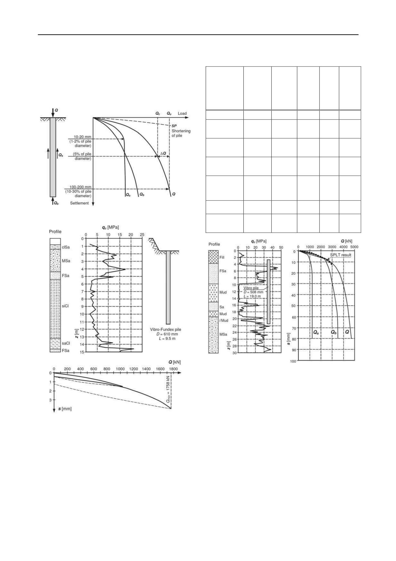
          precisely defined (Fig. 1). Possibly, some reserve


            ∆Q


          may be
        
        
          included in relation to critical load


            Q


            c


          (see Gwizdala 1997).
        
        
          Comparison of bearing capacities calculated by various
        
        
          methods reveals significant differences. Exemplary results of
        
        
          calculations for Vibro pile and for data presented in Fig. 2 are
        
        
          collated in Table 1.
        
        
          Figure 1. Generalized load-settlement curves of pile
        
        
          Figure 2. Data and static load test result of Vibro-Fundex pile, taken
        
        
          into calculation analysis
        
        
          Currently big pressure is put on the development of
        
        
          calculation methods based on direct results of in situ tests, e.g.
        
        
          CPTU tests and making use of load-transfer


            t-z


          i


            q-z


          functions.
        
        
          Such method has been proposed by Gwizdala and Steczniewski
        
        
          2007 (see example shown in Fig. 3) and for screw displacement
        
        
          piles by Krasinski 2012.
        
        
          The problem becomes much complex for the piles installed
        
        
          in layered soils with highly diverse strength parameters. In such
        
        
          cases reliable results can be obtained from static load tests
        
        
          (SPLT).
        
        
          Table 1. Static load test and calculation results for Vibro–Fundex pile
        
        
          Method
        
        
          Bearing
        
        
          capacity
        
        
          based on
        
        
          characte-
        
        
          ristic
        
        
          parameters
        
        
          [kN]
        
        
          Corre-
        
        
          lation
        
        
          coeffi-
        
        
          cients
        
        
          Chara-
        
        
          cteristic
        
        
          bearing
        
        
          capacity


            R


            c;k


          [kN]
        
        
          Partial
        
        
          resis-
        
        
          tance
        
        
          factor


            t


          Calcula-
        
        
          ted
        
        
          bearing
        
        
          capacity


            R


            c;d


          [kN]
        
        
          Design load


            Q


            r


          –
        
        
          –
        
        
          –
        
        
          –
        
        
          1034.0
        
        
          PN-83/B-
        
        
          02482
        
        
          based on SPLT
        
        
          1758.0
        
        
          (


            R


            c


          =


            Q


            max,SPLT


          )
        
        
          –
        
        
          –


            k


          = 0.8
        
        
          1406.0
        
        
          EN 1997-1;
        
        
          2004
        
        
          based on SPLT
        
        
          1758.0
        
        
          (


            R


            c


          =


            Q


            max,SPLT


          )


          1
        
        
          = 1.4


          2
        
        
          = 1.4
        
        
          1256.0
        
        
          1.1
        
        
          1142.0
        
        
          EN 1992-2;
        
        
          2007
        
        
          (DIN 1054)
        
        
          2378.0


          3
        
        
          = 1.4


          4
        
        
          = 1.4
        
        
          1699.0
        
        
          1.1
        
        
          1545.0
        
        
          LCPC
        
        
          Bustamante
        
        
          & Gianeselli
        
        
          (1982)
        
        
          1980.0


          3
        
        
          = 1.4


          4
        
        
          = 1.4
        
        
          1414.0
        
        
          1.1
        
        
          1285.0


          – method
        
        
          API (1984)
        
        
          1538.0


          3
        
        
          = 1.4


          4
        
        
          = 1.4
        
        
          1098.0
        
        
          1.1
        
        
          998.0
        
        
          Gwizdala &
        
        
          Steczniewski
        
        
          (2007)
        
        
          2308.0


          3
        
        
          = 1.4


          4
        
        
          = 1.4
        
        
          1648.0
        
        
          1.1
        
        
          1498.0
        
        
          Figure 3. Example of Vibro pile calculation results obtained from load-
        
        
          transfer functions method (Gwizdala and Steczniewski 2007)
        
        
          2. EXAMPLES OF IN SITU TESTS ON DRIVEN
        
        
          DISPLACEMENT PILES
        
        
          Driven displacement piles are applied for constructions
        
        
          transmitting large loads and when small settlements are
        
        
          required, especially plastic settlements for designed load range.
        
        
          Very good characteristics of subsoil-pile interaction are
        
        
          obtained for driven cast-in-place displacement piles such as
        
        
          Virbo, Vibro-Fundex and Franki. (Fig. 3, 4 and 5).
        
        
          2.1.


            Tests on Vibro and Franki piles under bridge object of A1


            highway


          In the frame of reconnaissance works for foundation of access
        
        
          flyover roads to large bridge over the Vistula river some tests on
        
        
          Vibro and Franki piles have been carried out. Vibro piles have
        
        
          the diameter of 508/560 mm and the length 25.4 m whereas
        
        
          Franki piles 560 mm and 23.5 m respectively. In Fig. 4
        
        
          geotechnical conditions in the form of CPTU characteristics and
        
        
          settlement curves obtained from load tests are presented. Load –