2745
Technical Committee 212 /
Comité technique 212
2.8 m were installed to depths of 65 m and 95 m. Load testing
of the barrettes comprised two levels of Osterberg cells in each
test barrette with each level of cells designed to achieve a bi-
directional load of up to 83 MN. The Osterberg cells were
positioned to measure performance of the lower 20 m
(approximately) of the barrettes .
The remaining instrumentation for each test barrette included
strain gauges and tell-tales as well as a displacement transducer
located in the rock below the toe in order to directly measure the
displacement of the rock at this location. The displacement
transducer at the toe of the barrettes was used to make a direct
measurement of compression of the ground immediately below
the toe.
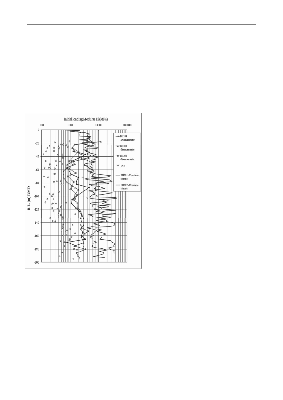
Figure 2 comparison of modulus values form UCS tests, pressuremeter
and cross-hole seismic tests
3.5 Comparison of modulus values
The results of the three pressuremeter tests shown in Figure 2
show values of modulus of between about 1200 MPa and 2000
MPa at the depths corresponding to the bases of the barrettes.
Reducing the modulus values from the cross-hole seismic tests
by a factor of five gives results in the range of 1000 MPa to
4000 MPa (with the highest values being obtained in layers of
gypsum).
Back analysis of the test data from the instrumented
barrettes indicates a modulus (Ei) of the soft rock below the toe
of between 1200 MPa and 1500 MPa.
The most optimistic assessment of the UCS results at the
depths considered is about 600 MPa.
There is good agreement between modulus values from the
test barrettes, the pressuremeter results and factored-down
cross-hole seismic results. This gave confidence in the adoption
of a value for final design. Adoption of the laboratory test
results would have led to an overly conservative design (and, in
fact, would have shown the design of a pile-supported raft to
meet the settlement criteria to be impractical).
4 TALL TOWERS ON DEEP ALLUVIAL DEPOSIT
4.1 Ground conditions and original investigation methods
The author has recently been involved in the design of piled
rafts for a series of towers from 50 levels to 80 levels. The site
is located on a river flood plain and is underlain by very deep
alluvial deposits comprising predominantly very dense silty
sands and hard sandy silts.
The original ground investigation undertaken by others
included SPT tests to about 100 m depth, with SPT refusal
(more than 50 blows for less than 150 mm penetration)
occurring for all tests below about 30 m depth. It was therefore
not possible to make a reliable estimate of ground stiffness from
the SPT results.
Menard pressuremeter testing was also performed. The
Menard pressuremeter tests gave unrealistically low results,
possibly the result of relatively poor drilling methods which
caused significant disturbance of the borehole. Cone
penetrometer testing was also attempted but the cone refused at
relatively shallow depth. Continuation of cone testing beyond
refusal depth using predrilling was not successful as cone
refusal occurred within 0.5 m of the base of the predrill.
The information from the geotechnical investigation
(undertaken by others) was not sufficient to be able to reliably
design the foundations for the towers. In addition, preliminary
calculations indicated that based on a reasonable interpretation
of the ground investigation data, a pile only or pile raft solution
of sufficient capacity and dimensions to support the towers
could not be practically installed using available piling
technology.
4.2 Cross-hole seismic and pile load tests
The author requested cross-hole seismic testing to be
undertaken to supplement the original ground investigation data.
Two cross-hole seismic tests were carried out to about RL 60 m
(CHST1 and CHST2). The two deeper cross-hole seismic tests
(CHST3a and CHST4a) were carried out to below RL 10 m.
Figure 3 compares estimates of
Young’s
modulus assessed from
the various tests. The cross-hole seismic modulus results have
been reduced by a factor of five to account for the increased
strain levels appropriate to pile performance.
The resulting design line used for the analysis of the pile
rafts is also shown in Figure 3.
The author also recommended that pile load testing be
undertaken to provided additional information with respect to
the properties of ground in the vicinity of the pile shaft and
below the toe of the test pile. To maximize the amount of
information from the pile testing, Osterberg cell testing using
two levels of Osterberg cells was recommended. By using two
levels of cells, the shaft resistance between the upper and lower
cells could be directly measured without reliance on
interpretation of strain gauges which can be problematic. By
placing the lower Osterberg cell close to the base of the pile, the
direct measurement of the base performance of the pile could
also be measured directly. Interpretation of this load versus
settlement performance would allow an estimate of the modulus
of the ground below the toe of the test pile.
Load testing was carried out on a pile of 1.2 m diameter and
about 47 m length, constructed from the basement excavation at
about 20 m below surrounding ground level.
The results of the pile load test indicated an unknown but
significant thickness of debris at the base of the pile, which
made estimation of the modulus of the soil below the toe of the
pile more difficult and less certain. An estimate of the modulus


