2747
Non-Conventional Pile Loading Tests in Vietnam
Non conventionnelles essais de chargement de pieux au Vietnam
Hai N.M.
Faculty of Civil Engineering, Thu Dau Mot University, Vietnam
Dao D.H.
Faculty of Bridge and Road Engineering, Da Nang University of Technology, Vietnam
ABSTRACT: Two bidirectional tests used single-level jacks were performed on strain-gauge instrumented bored piles in Da Nang
City, Vietnam. The soil profile consists of medium dense silty sand followed by thick firm clay underlain by highly weathered
sandstone. The piles, 800 mm and 1,000 mm in diameter, were installed to 34 m depth and constructed using bucket drill technique
with bentonite slurry. The jack assemblies were attached to a reinforcing cage above the pile toe from 0.5 m through 0.8 m. The static
loading tests were performed 21 days after constructed piles. The maximum bidirectional test loads ranged from 3.8 through 4.8 MN
and the measured maximum upward and downward movements ranged from about 3 through 28 mm and 7 through 49 mm,
respectively. The analysis of strain-gauge records showed that the Young’s modulus values were about 25 and 22 GPa as calculated
on the nominal cross section of the 800 and 1,000 mm diameter piles, respectively, the shaft resistances were strain-softening, and the
pile toe stiffness was very soft and essentially linear. The measured load distribution corresponded to effective stress proportionality
coefficients, ß, of about 0.2 through 0.3.
RÉSUMÉ : Deux essais bidirectionnels utilisés à un niveau sur les pieux instrumentés à jauges de contrainte ont été effectuées à Da
Nang, Vietnam. Le profil géologique du site se compose d’une couche de sable limoneux moyennement dense au-dessus d’une
couche d’argile ferme épaisse reposant sur les grès très altérés. Les pieux de 800 mm et 1000 mm de diamètre, ont été installés
jusqu’à 34 m de profondeur en utilisant la technique de seau de forage avec les coulis de bentonite. Les ensembles de vérins étaient
attachés à une cage d'armature de 0,5 m à 0,8 m au-dessus de la pointe des pieux. Les essais de chargement statique ont été effectués à
21
ème
jours après l’exécution des pieux. Les charges maximales des essais bidirectionnels varient de 3,8 à 4,8 MN et les déplacements
maximaux mesurés vers le haut et vers le bas varient respectivement de 3 à 28 mm et de 7 mm à 49 mm. L'analyse des données
enregistrées des jauges de contrainte a montré que le module de Young était d'environ 25 à 22 GPa, tel que calculé sur la section
nominale des 800 à 1.000 mm pieux, respectivement, les résistances se ramollissaient et la rigidité de la pointe des pieux était très
faible et essentiellement linéaire. Le coefficient de proportionnalité (
) entre la charge mesurée et la contrainte effective
correspondante était de 0.2 à 0.3.
KEYWORDS: bidirectional test, bored piles, strain-gages, shaft and toe resistances, strain-softening, movements.
1 INTRODUCTION
The 12-story Sea Bank Building is built over a 7.35 m by 20.30
m area among existing high-rise Buildings in Da Nang City,
Vietnam. The foundations were placed on 800 and 1,000 mm
diameter bored piles constructed to 34 m depth designed for
working loads of 3.8 and 4.8 MN, respectively..
To validate the capacity of the piles, a pile loading test
programme was carried out by means of the bidirectional O-cell
test (Osterberg 1989) as being the best suitable for the limited
project area. Both test piles were equipped with vibrating wire
strain gages.
The results of the tests are presented and correlated to the
soil conditions of the site. The test data and back-analyses are
considered to be of interest beyond the design of the piled
foundations for the Sea Bank Building.
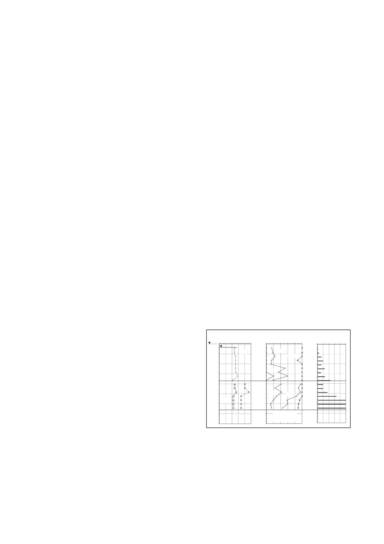
2 SOIL PROFILE
The soil profile consists of medium dense silty sand to 18.5 m
depth followed by 14.5 m thick firm clay underlain by highly
weathered sandstone. Figure 1 shows the distribution of water
content, consistency limits, grain size distribution, and SPT N-
indices. The natural water content ranges from about 20 %
through about 30 %. The density of the silty sand above the firm
clay is 1,940 kg/m
3
(from w
n
= 25 %). Total saturated density is
about 1,950 kg/m
3
throughout the firm clay.
0
5
10
15
20
25
30
35
40
0 10 20 30 40 50
DEPTH (m)
WATERCONTENT (%)
+5.0 m
+ 3.5 m GWL
w
n
w
P
w
n
w
L
0
5
10
15
20
25
30
35
40
0 20 40 60 80 100
DEPTH (m)
CLAY
SAND
CLAY
SILT
SILT
GRAINSIZEDISTRIBUTION
SPTN-INDICES
(blows/0.3m)
0 20 40 60 80100
0
5
10
15
20
25
30
35
DEPTH (m)
40
HIGHLY
WEATHERED
SANDSTONE
Figure 1. Water contents, grain size distrib., and SPT N-indices
Average of SPT N-indices is about 23 blows/0.3m to 27 m
depth and more than 100 blows/0.3m below this depth. The
underlain layer is highly weathered sandstones with rock quality
designation of 0% through 10% and total core recovery of 12
through 21 % to 50 m depth below the original ground surface.
Below this depth, the rock quality designation and total core
recovery are 13 through 30% and 20 through 80%, respectively.
The groundwater table is located at a depth of about 1.5 m
below the ground surface.
Non-Conventional Pile Loading Tests in Vietna
Essais non conventionnels de chargement de pieux au Vietnam
Hai N.M.
Faculty of Civil Engineering, Thu Dau Mot University, Vietnam
Dao D.H.
Faculty of Bridge and Road Engineering, Da Nang University of Technology, Vietnam
ABSTRACT: Two bidirectional tests used single-level jacks were performed on strain-gauge instrumented bored piles in Da Nang
City, Vietnam. The soil profile consists of medium dense silty sand followed by thick firm clay underlain by highly weathered
sandstone. The piles, 800 mm and 1,000 mm in diameter, were installed to 34 m depth and constructed using bucket drill technique
with bentonite slurry. The jack assemblies were attached to a reinforcing cage above the pile toe from 0.5 m through 0.8 m. The static
loading tests were performed 21 days after constructed piles. The maximum bidirectional test loads ranged from 3.8 through 4.8 MN
and the measured maximum upward and downward movements ranged from about 3 through 28 mm and 7 through 49 mm,
respectively. The analysis of strain-gauge records showed that the Young’s modulus values were about 25 and 22 GPa as calculated
on the nominal cross section of the 800 and 1,000 mm diameter piles, respectively, the shaft resistances were strain-softening, and the
pile toe stiffness was very soft and essentially linear. The measured load distribution corresponded to effective stress proportionality
coefficients, ß, of about 0.2 through 0.3.
RÉSUMÉ : Deux essais bidirectionnels utilisés à un niveau sur les pieux instrumentés à jauges de contrainte ont été effectués à Da
Nang, Vietnam. Le profil géologique du site se compose d’une couche de sable limoneux moyennement dense au-dessus d’une
couche d’argile ferme épaisse reposant sur les grès très altérés. Les pieux de 800 mm et 1000 mm de diamètre, ont été installés
jusqu’à 34 m de profondeur en utilisant la technique de seau de forage avec les coulis de bentonite. Les ensembles de vérins étaient
attachés à une cage d'armature de 0,5 m à 0,8 m au-dessus de la pointe des pieux. Les essais de chargement statique ont été effectués à
21
ème
jours après l’exécution des pieux. Les charges maximales des essais bidirectionnels varient de 3,8 à 4,8 MN et les déplacements
maximaux mesurés vers le haut et vers le bas varient respectivement de 3 à 28 mm et de 7 mm à 49 mm. L'analyse des données
enregistrées des jauges de contrainte a montré que le module de Young était d'environ 25 à 22 GPa, tel que calculé sur la section
nominale des 800 à 1.000 mm pieux, respectivement, les résistances se ramollissaient et la rigidité de la pointe des pieux était très
faible et essentiellement linéaire. Le coefficient de proportionnalité (
) entre la charge mesurée et la contrainte effective
correspondante était de 0.2 à 0.3.


