2757
Technical Committee 212 /
Comité technique 212
Research on the Load-Bearing Behaviour of Bored Piles with Different Enlarged Bases
18
th
International Conference on Soil Mechanics and Geotechnical Engineering, Paris 2013
3
3
TEST SEQUENCE
After complete installation of the appropriate test pile (see
Installation- /Soil parameter Table 1):
4
EVALUATION OF THE RESULTS
For the evaluation of the results and the comparative analysis,
the three tests per pile were averaged. The calculated average values
were used as the representative values for the respective pile models
for all of the following comparisons and computations.
Table 1 shows that all three models had comparable mobilized
skin frictions from 6131.1 to 762.0 N. The skin friction appears to
be a constant value with it’s proportion of the load decreasing
greatly with increasing base enlargement so that a shift in the
resistance occurs from a skin friction/point bearing to a
predominantly point bearing pile. The existing technical
assumption/theory that there is an “arching effect” regarding the
stress distribution with a base enlargement by activating higher skin
friction stresses cannot be substantiated by this test series.
1.Placement /Compaction 1. Layer
2.Placement /Compaction 2. Layer
3.Centering/Plumbing test pile in the container
4.Placement /Compaction 3.-6. Layer,
Table 1. Installation- /Soil parameter
Installation- /Soil parameter
d
Container
[cm]
70
h
layer
(1-6)
[cm]
14.5
M
layer
(1-6)
[g]
15867
D
[g/cm³] 1.71
g
s
[g/cm³] 2.65
I
D
[-]
0.74
Table 2. Results of Test Models 1xD, 2xD, 3xD, Comparison of results
with and without skin friction
Skin friction (R
S
)
Test
Pile
Point bearing (R
b
)
+Skin friction (R
S
)
Point
bearing
Absolute Relative
R
b+s
[N]
R
b
[N]
[N]
[%]
Model
1xD
1645.4
1032.3
613.1
37.2
Model
2xD
4505.2
3743.2
762.0
17.1
Model
3xD
9684.5
9013.1
671.4
6.8
in the test soil (dense sand), the experimental container (steel
cylinder) was centered under the cross beam and hydraulic press.
After installation of the measuring bridge (See Figure 6) a seating
load, F
i
= 250 N, was applied to eliminate any slack in the loading
system and to adjust the strain gauge.
The experimental models 1xD and 2xD were loaded in
increments of 250N, and model 3xD in 500N steps. After each
increment of loading the load was held for 10 minutes. Settlement
readings were made after 0, 1, 2, 3, 5 and 10 minutes. The failure
criterion for the test loadings was taken to be when the pile sank
continuously into the soil under a constant load.
According
to
FRANKE
the
evaluation
of
the
FRANKE/GARBRECHT investigations shows that for bearing
structures with acceptable deformation ranges of 2 to 4 cm and
different loadings, it is possible to equalize settlements by the use of
pile foot base enlargement
(see Table 4).
Table 3. Comparison of the results of model tests 1xD, 2xD, 3xD
Test Pile
1xD
2xD
3xD
Base diameter
[mm]
36
72
108
Contact area
[mm²] 1017.88 4071.5 9160.88
Settlement limit s
gr
[mm]
3.6
7.2
10.8
R(s
gr
)
b+s
from tests
[N]
1645.4
4442.5
9645.9
Proportional increase
related to the 1xD-pile
[%]
-
270.0% 586.2%
R(s
gr
)
b
from tests
[N]
1032.3
3743.2
9013.1
Proportional increase
related to the 1xD-pile [%]
-
362.6% 873.1%
Figure 6. Test Set-Up
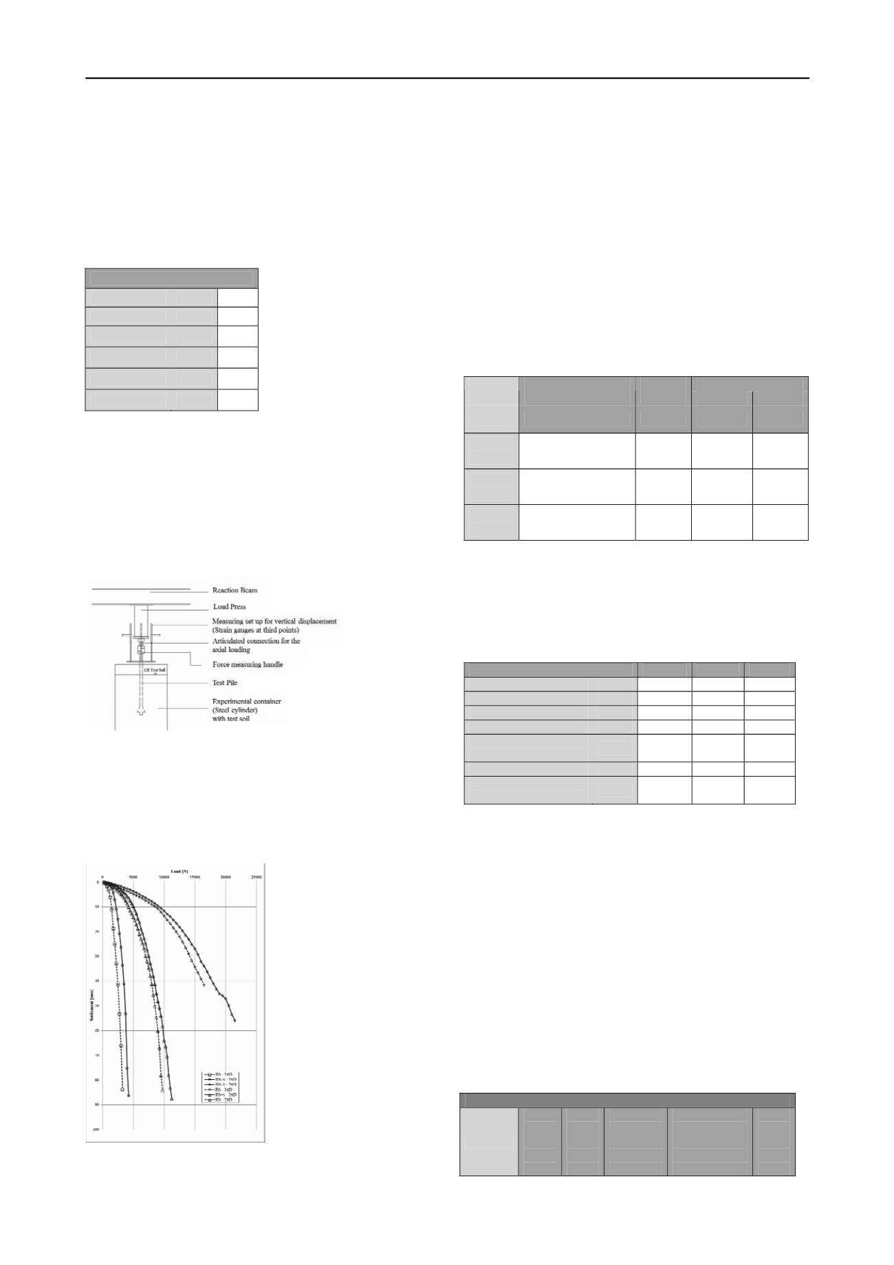
3.1
Results of the Load Tests
On the basis the measured values of the applied loads and
associated vertical displacements, a graphic evaluation of the
various test loads was made. The bearing resistance dependant
on the pile settlement is illustrated in the following (see figure
7) by the average resistance-settlement curve (average values of
the R
b+s
and R
b
test loadings).
5
COMPARISON WITH IN SITU TESTS
For the evaluation of the results, there are at present only the
investigations by FRANKE/GARBRECHT in the form of full-scale
tests, which are drilled piles 6 to 14 m long with pile (b) and pile
base diameters (b
f
) from 1100 to 2100 mm hat were manufactured
with and without base enlargements in medium dense sands and
were load tested with deactivated skin friction (using a bentonite
filled ring gap) (see Table 3).
The results of the investigations by Franke/Garbrecht indicate that
the ratio of the breaking stress for the enlarged to the normal pile
amounts to approximately 0.94 to 0.95 (see Table 4 σb(s
gr
)
(1)
to
σb
f
(s
gr
)
(1)
). This with the reducing coefficient for characteristic pile
resistances, α
enlarged
= 0.75, verifies the manufacturer’s partial safety
factor, γ > 1.25 (see Eq. 1 resp. Eq. 2 / Table 4),
R
bf
(s
gr
) / (R
bf
(s
gr
) · 0,75) > 1,25
(Eq. 1)
σb
f
(s
gr
)
(1)
/ (σb
f
(s
gr
)
(1)
· 0,75) > 1,25
(Eq. 2)
the acceptable safety representative of the researched pile foot base
enlargement.
Table 4. Comparison of the results of Franke/Garbrecht with own Tests
Figure 7. Load Test Resistance-Settlement Curves, R
b+s
and R
b
(average
values in each case from 3 test load trials)
FRANKE/GARBRECHT
Pile
b
resp.b
f
Ratio
b
f
resp.
b
[-]
Pile foot
base area
[m²]
σb(s
gr
)
(1)
resp.
σb
f
(s
gr
)
(1)
[N/mm2]
σb(s
gr
)
(1)
to
σb
f
(s
gr
)
(1)


