2765
Technical Committee 212 /
Comité technique 212
design. There has been much work done on pile-soil interaction.
A relatively less work has been done on the unified analysis that
includes both piled foundation and superstructures. Because the
mechanism of load transfer between piled foundation and
superstructures involves a complex interaction between
structures, raft, piles, and surrounding soil. The analysis process
is affected by many factors such as: column and wall geometry,
design load, raft and pile group geometry, soil properties, and
interaction between different structure elements. Accordingly,
there are currently no methods available to predict behavior of
the entire structures due to the difficulty and uncertainty in
quantifying these factors.
Therefore, the overall objective of this study focuses on
application of interactive analysis method for predicting
behavior of entire structures. A series of numerical analyses was
performed to verify the interactive analysis routine in
comparison to
the unified analysis method. For this purpose, the
three-dimensional (3D) Finite-Element (FE) analysis has been
carried out. For the unified analysis of super and sub-structures,
the numerical analyses were performed via the FE code
PLAXIS 3D foundation, with column, floor and piled raft
foundation systems placed on a typical weathered soil in Korea.
3.2 Interactive analysis
In most of the design field, the analysis of super-structure was
conducted without modeling the foundation system and the
foundation was designed without considering the rigidity of
super-structure. It may result in overestimation of forces, the
bending moment, settlement of super- and sub-structure.
In this study, the interactive analysis procedure is proposed for
predicting the behavior of entire structure by considering soil-
foundation stiffness and rigidity of super-structure. The
procedure of interactive analysis in this study include the
following steps:
(a) Compute the reaction force of structure-foundation
interface in fixed boundary condition.
(b) Construct the CSM(coupled stiffness matrix) of soil and
foundation using reaction force.
(c) Re-compute the reaction force of interface in CSM
boundary condition.
(d) Calculate the member force and displacement of
foundation.
(e) Check the convergence of member force and displacement
at interface node from step (c) and (d).
The procedure described above is iterated until the error
between the super- and sub-structure displacements falls within
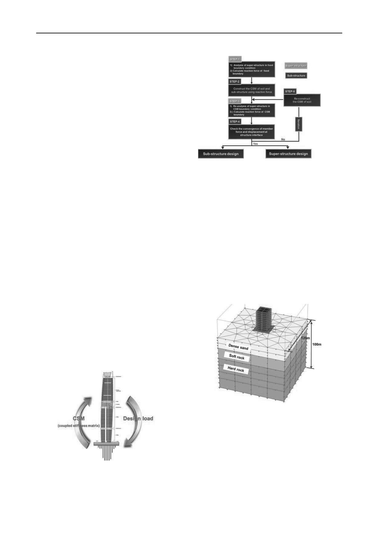
a tolerance limit. Figure 4 shows a schematic diagram and
flowchart of the interactive analysis.
(a) Schematic figures of interactive analysis
(b) Flowchart of interactive analysis
Figure 4. Interactive analysis between super- and sub-structure
3.3 Verification of proposed method with finite-element analysis
In this section, the validation of the proposed method with
numerical analysis is discussed. The three-dimensional finite-
element mesh used for the structure-foundation-soil system is
shown in Figure 5. The structure consists of columns, 10 floors,
a raft, and 25 identical vertical piles, which are spaced by 2.5m
(= 2.5D, where D is a pile diameter).
The piles are 1m in diameter and 10m in embedded length. A
square raft has a width of 15m with fixed pile head conditions.
The columns are 3.5m in length and 0.6m in width. At the left-
and right-hand vertical boundaries, lateral displacements were
restrained, whereas fixed supports were applied to the bottom
boundaries. The specified initial stress distributions should
match with a calculation based on the self-weight of the
material. After the initial step, the applied loading was
simulated by a self-weight of super-structure.
(a) Structure-foundation-soil system


