2774
Proceedings of the 18
th
International Conference on Soil Mechanics and Geotechnical Engineering, Paris 2013
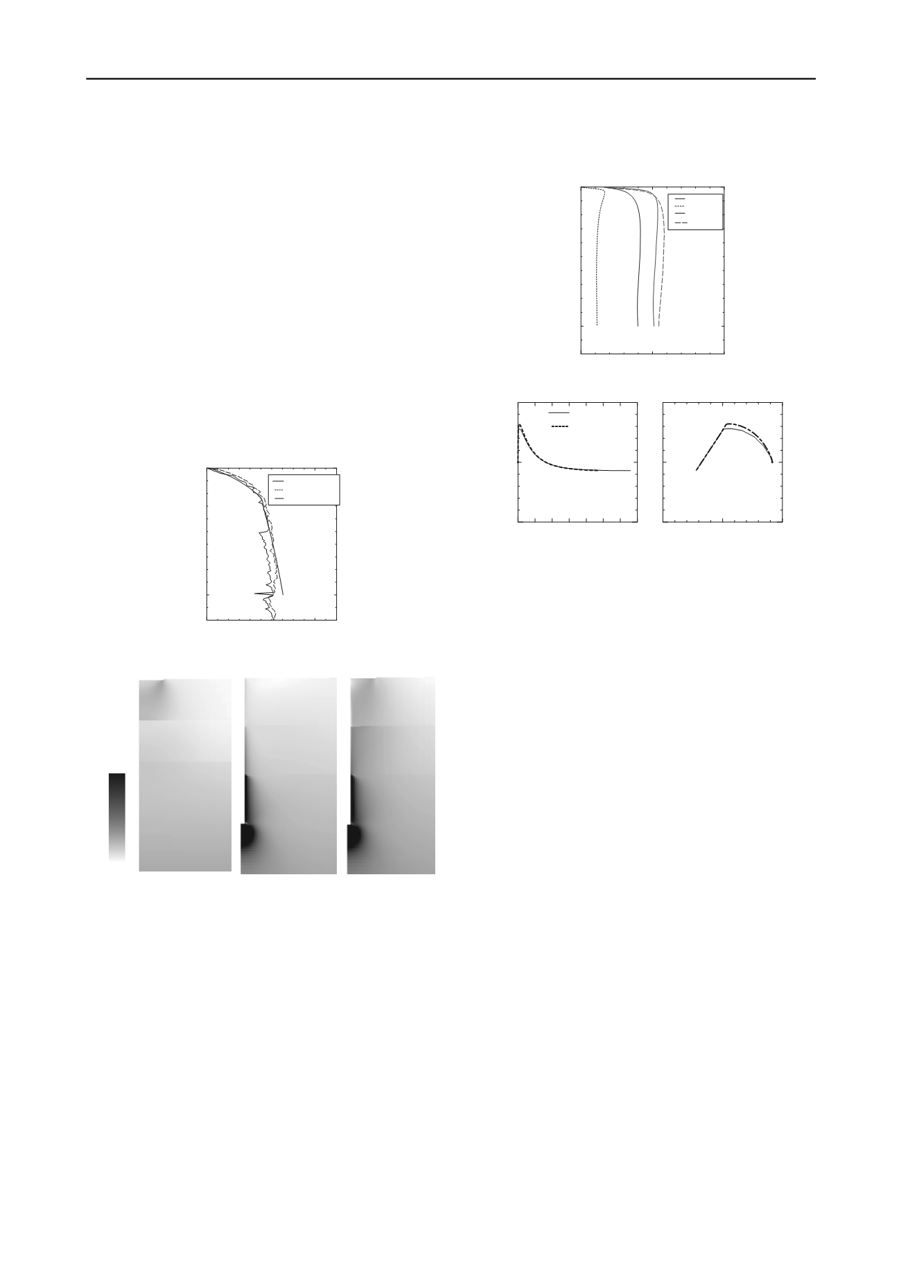
they agree with the experimental results. In general, as
discussed above, the amount of settlement for the piled raft
foundation is less than the sum of that for the pile and the raft
because the friction around the upper pile is not effective. In this
case, in both the experiment and the simulation, the combined
load of the pile and the raft is the same as that of the piled raft
foundation.
Figure 11 shows the distribution of the mean effective stress for
the raft, pile, and piled raft foundations. The stresses range from
0 to 300 kPa. The soil parameters around the pile are set to
represent clay 1, sand 1, and sand 2. An increase in the mean
effective stress can be seen in clay 1 for Case 1, sands 1 and 2
for Case 2, and sands 1 and 2 and clay 1 for Case 3. The stress
increase in sand 1 is particularly large for Case 3. The reason
why the combined load for the pile and the raft is the same as
the load for the piled raft foundation is that the increased mean
effective stress is transmitted deeper into the ground by the
effects of both the raft and the pile. The mechanism by which
the total load is carried can be better understood by considering
the shear behavior of both clay and sand and the influence of the
multi-layered structure.
0
10000
100
0
Settlement (mm)
Load (kN)
Piled raft (Exp.)
Pile + raft (Exp.)
Pile + raft (Sim.)
Figure 10: Relationship between settlement and load
0kPa
300kPa
clay1
clay1
clay1
sand1
sand1
sand1
sand2
sand2
sand2
Figure 11: Distribution of mean effective stress
6 CASE STUDY OF COMBINED BEARING CAPACITY
In this phase of the research, additional case studies were
performed on the combined bearing capacity between pile, raft
and piled raft foundations. Clay 1, which is considered a
relatively soft naturally sedimented soil, is assumed for all soils
in Figure 12, which shows the simulation results. As can be
seen in the figure, the bearing capacity of the piled raft
foundation is slightly larger than that of the summation between
the pile and raft. Figure 13 shows the element behavior at the A
element of Figure 2, which is near the pile. The behavior near
the pile can be seen in the softening observed in both the pile
and piled raft foundations. As for the mean effective stress
space, it was found that the stress of the piled raft foundation
was slightly larger than that of the pile. This is because the
confined effect of the raft is sufficient. It should be noted that
this is a relatively simple example and that additional research
into multi-layer soil systems, as well as the effects of soil
materials, will be necessary in the future.
0
1000
2000
100
0
Settlement (mm)
Load (kN)
Raft
Pile
Raft+Pile
Piled raft
Figure 12. Relationship between settlement and load
0.2 0.4 0.6
0
10
20
10
20
0
10
20
Deviator stress (kPa)
Shear strain (
%
)
Mean effective stress (kPa)
Pile
Piled raft
Figure 13. Element behaviors
7 CONCLUSIONS
Simulations of the bearing capacity of raft, pile, and piled raft
foundations were performed and the results were compared with
those obtained from experimental measurements. Material
parameters and initial conditions were determined by laboratory
testing of specimens collected in the field. The numerical
simulations were found to reproduce the experiment data well.
These results indicated that the combined load for the pile and
raft was the same as the load for the piled raft foundation, and
this was confirmed by both experiments and simulations. We
believe the reason for this is that the mean effective stress is
transmitted to deeper parts of the ground by the combined
presence of both the raft and the pile. However, more detailed
numerical simulations will be required to fully clarify this issue.
8 CONCLUSIONS
The authors wish to express their sincere thanks to the
Geotechnical Research Group, Nagoya University, Japan for
their advice during the numerical analysis.
9 REFERENCES
Asaoka, A., Nakano, M. and Noda, T. (2000): Superloading
yield
surface concept for highly structured soil behavior,
Soils and
Foundations
, 40(2), pp. 99-110.
Asaoka, A., Noda, T., Yamada, T., Kaneda, K., and Nakano,
M.
(2002): An elasto-plastic description of two distinct volume change
mechanisms of soils,
Soils and Foundations
, 42(5), pp. 47-57.
Asaoka, A., Nakano, M. and Noda, T. (1994): Soil-water
coupled
behavior of saturated clay near/at critical state,
Soils and
Foundations
, 34(1), pp. 91-105.
Honda, T., Hamada, J., Tanikawa, T., Yamada, T., Tsuchiya, T. and
Yamashita, K. (2012):
Large-scale load tests on bearing
capacity of piled raft foundations, Testing and Design Methods for
Deep Foundations, IS-Kanazawa, pp.497-502.
Kaneda, K., Shigeno, Y., Hamada, J. and Tanikawa, T. (2012):
Numerical Simulation of Load Tests on the Bearing Capacity of
Piled Raft Foundations, Testing and Design Methods for Deep
Foundations, IS-Kanazawa, pp.491-496.


