2776
Proceedings of the 18
th
International Conference on Soil Mechanics and Geotechnical Engineering, Paris 2013
When the reinforced concrete compression member (e.g.,
reinforced concrete pile) is wrapped with the fiber reinforced
plastic, the axial load carrying capacity of the pile is increased
due to the confinement provided by the fiber reinforced plastic.
Such an effort to develop efficient concrete Column wrapped
with FRP has been continued from the early of 20th century.
Hybrid FRP-concrete composite pile (HCFFP) is consisted
of pultruded FRP unit module, filament winding FRP which is
in the outside of mandrel composed of circular shaped assembly
of pultruded FRP unit modules, and concrete which is casted
inside of the circular tube shaped hybrid FRP circular tube as
shown in Figure 1. Therefore, pultruded FRP can increase the
flexural load carrying capacity, and the filament winding FRP
tube and concrete filled inside of it can increase the axial load
carrying capacity.
In this study, in order to use as the pile for foundation
construction, we estimated the structural performance of
HCFFP through the uniaxial compression tests. Mechanical
properties of the FRP material are investigated. Based on the
reviews of previous research results and the experimental
studies conducted in this study, equation for predicting the
ultimate axial compressive strength of the HCFFP is suggested.
1 HYBRID FRP-CONCRETE COMPOSITE
COMPRESSION MEMBER
In this study, improved HCFFP system, an exterior filament
winding FRP layer component and an interior pultruded FRP
with concrete, is proposed as shown in Figure 1.
Pultruded
FRP
Concrete
Filament
Winding
FRP
D
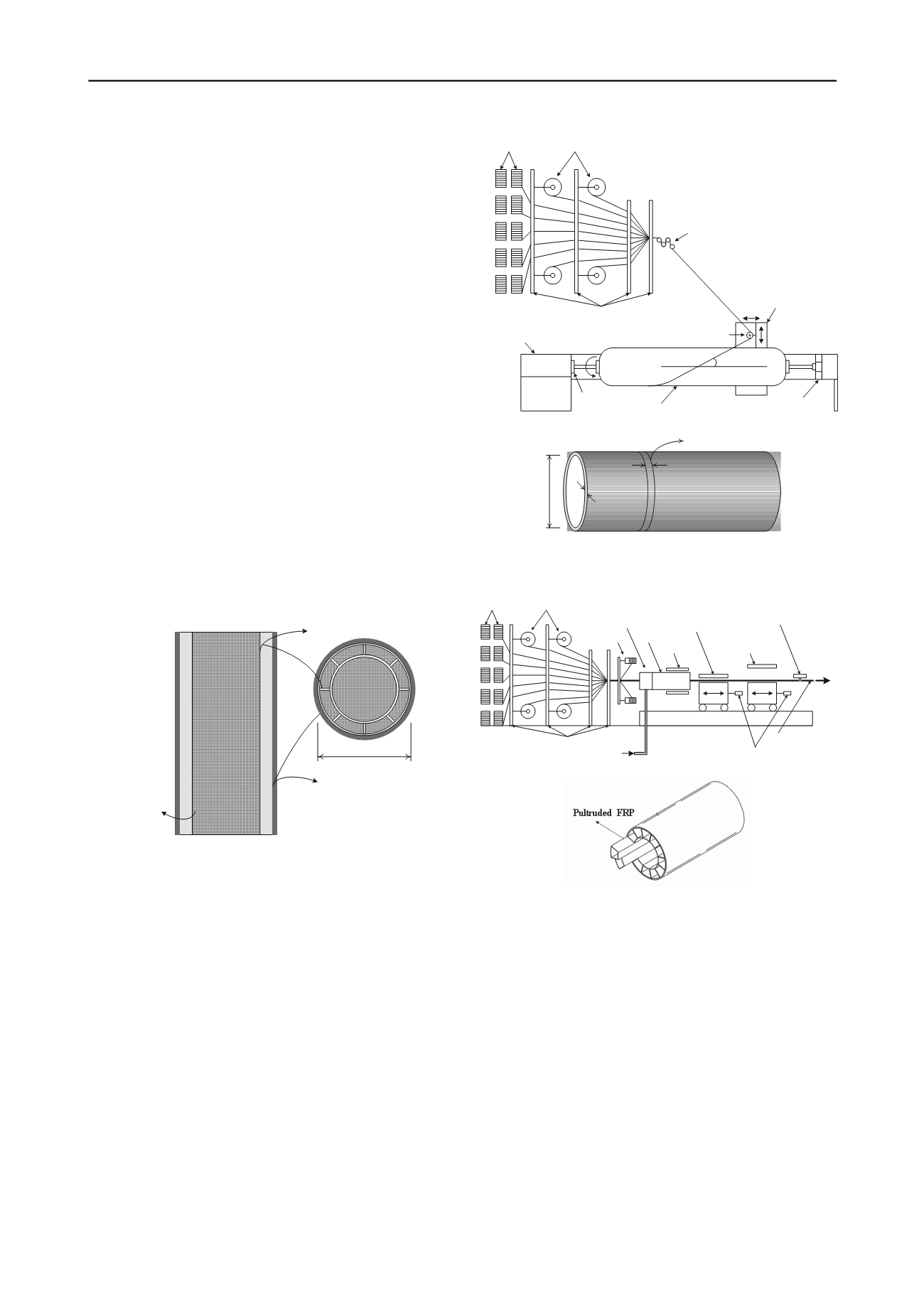
Figure 1 Hybrid FRP-concrete composite pile (HCFFP).
The exterior layer consists of a multilayer filament winding
FRP. The interior reinforced concrete consists of pultruded FRP
and concrete. Filament winding FRP may have various cross-
sectional dimensions to satisfy the structural design
requirements. A cylindrical concrete core is located in the
filament winding FRP and pultruded FRP, where the interior
pultruded FRP and the exterior filament winding FRP provide
axial and circumferential reinforcement, respectively, for the
concrete core.
The specimens of HCFFP members, which are the FRP
circular tubes that had been manufactured by filament winding
and pultrusion processes are shown in Figures 2 and 3,
respectively. Filament winding process is surfaces of revolution,
such as pipes, cylinders, and spheres. In filament winding,
continuous reinforcements, such as roving, are wound onto a
mandrel until the surface is covered and the required thickness
is achieved. Pultrusion is a continuous manufacturing process
used to manufacture constant cross section shapes with
unlimited length. Pultrusion is a cost effective process because
it achieves direct conversion of continuous fibers and resin into
a finished part. The fibers are continuously impregnated and
pulled through a heated die, where they are shaped and cured.
Creel Racks Tape Racks
Preforming Guides
Spindle
Headstock
Mandrel
Tailstock
Horiz. &Vert. Carriage
Delivery Eye
Tensioning Device
a
d
t
frp
b
frp
Cutting
Figure 2 Manufacture of the filament winding FRP specimen.
Creel
Racks
Mat
Racks
Preforming Guides
Resin Injection
Winder
Injection
Chamber
Die
Heaters
Puller
Engaged
Puller
Design Gage
Moving Cutoff Saw
Hydraulic Rams
Finished Product
Figure 3 Manufacture of the pultruded FRP specimen.
2 LABORATORY TEST RESULTS
2.1
Mechanical Properties of Materials
Dimension of the filament winding FRP tube and pultruded
FRP specimens are given in Table 1. A glass-fiber and a
polyester resin were used to manufacture the FRP. Compressive
strength of concrete was obtained from the uniaxial
compression tests at the age of 28 days. Material properties tests
of the filament winding FRP tube were split disk and
compressive tests and pultruded FRP were tensile test. The split
disk test of the FRP specimens was carried out at the Structures
Laboratory in Hongik University, Korea. A total of 9 specimens
were tested for the split disk test and the compressive test,
respectively. A total of 9 specimens are tested, 3 for 3 tests, as
given in Table 1.
The failure load, the ultimate strength, and the modulus of
elasticity are determined and summarized as shown in Table 2,


