2762
Proceedings of the 18
th
International Conference on Soil Mechanics and Geotechnical Engineering, Paris 2013
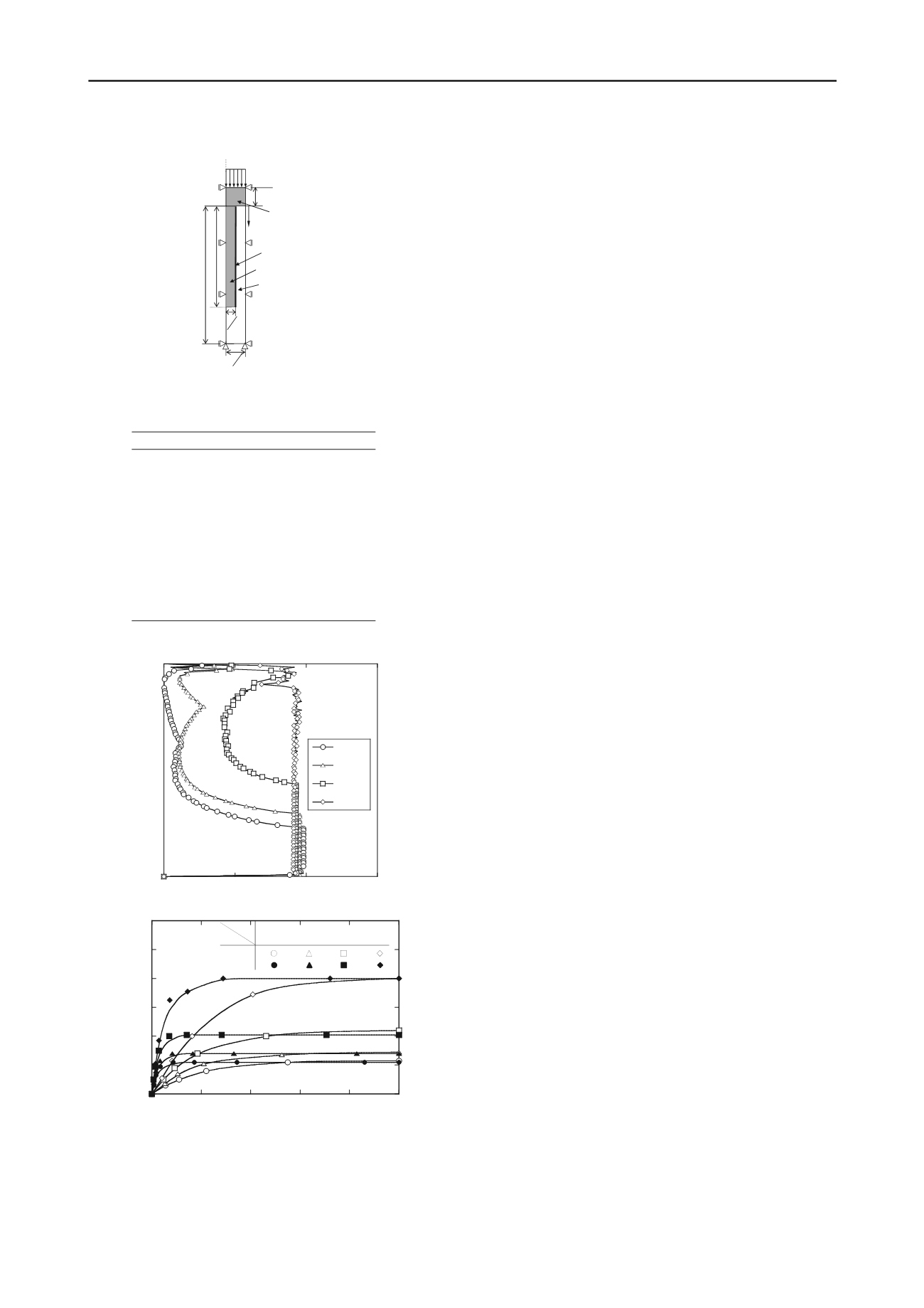
Figure8. Axi-symmetry analytic model
Table1. Material parameters for analysis
Figure9. Mobilized skin friction used in the different shear strength
Figure10. Time dependent tendency of friction mobilization
3.2
Tendency of skin friction mobilization
Figure 9 shows the relationships between degree of mobilized
skin friction and normalized column depth after primary
consolidation. Mobilized skin friction ratio was defined as the
ratio of the current mobilized skin friction to the full skin
friction resistance. Normalized depth was defined as the ratio
between the column depth from just below the shallow
stabilized ground and the column length. As shown in this
figure, full mobilized skin friction length
p
H
1
H
2
d
2
L
h
Column
Soft clay
CL
Shallow
stabilized
ground
z
Interface
reduced with an
in
tion can
also be moved upward in the co olidation process.
nd converged to the constant value in the consolidation process.
of Nagasaki University for their
dvice and encouragement.
Ber
Ishi
Ishi
Ishi
th
Mik
Yan
cal and Geoenvironmental Engineering
ASCE, 138(7),
789-798.
crease of interface friction coefficient.
Figure10 shows the relationships between the normalized
friction length and consolidation time by using different full
shear resistance of soil-pile interface and soil properties.
Normalized friction length means the ratio of full mobilized
skin friction length to the column length. Normalized
consolidation time was also defined as the ratio between the
current time and the time that excess pore water pressure
reached under 1 kPa in the soft clay. In all the conditions, full
mobilized skin friction length increased with elapsed time and
converged to the constant value. In this analysis, soil property
λ
has little influence on the full mobilized skin friction length. It
is considered that skin friction is mobilized around the soil –pile
interface acting relative displacement between pile and soft clay.
So there is some possibility that the equivalent raft eleva
Raft and Pile Soil
Interface
γ
sat
(kN/m
3
)
16.8
16.8
E
(kPa)
1.0
×
10
8
ν
0.30
0.15
λ
0.5 or 0.1
κ
0.1 or 0.02
c
'(kN/m
2
)
1.0
1
φ
'(
°
)
30
OCR
1
e
ini
(at
p
'=1kPa)
1.8
R
0.9,0.75,0.5,0.3
ns
4
CONCLUSION
In order to investigate the settlement behavior and skin friction
of floating type improved ground with shallow stabilization
during consolidation, loading model tests and full scale FEM
analysis were performed. From the results, It was clarifed that
vertical strain of soft clay in the upper part of the improved
portion was restrained by the combined effect of pile and raft.
Further, from the analytic results, it was also found that full
mobilization length of skin friction increased with elapsed time
.0
30
a
0.0
0.25
0.50
0.75
1.0
0
0.5
1
1.5
R
=0.90
R
=0.75
R
=0.50
R
=0.30
Normalized depth z
/H
1
Mobilized skin friction ratio
τ
/
τ
f
λ
=0.50
5
ACKNOWLEDGEMENTS
The authors wish to express their gratitude to many students, at
graduate school of Yamaguchi University, for their supports.
The first author is grateful to Prof. Y. Nakata of Yamaguchi
University for his support of image analysis and is also grateful
to Professor Noriyuki Yasufuku of Kyushu University and
Professor Kiyoshi Omine
a
6
REFERENCES
gado, D.T., Chai, J.C., Alfaro, M.C. and Balasubramaniam, A.S.
1994. Improvement Techniques of Soft Ground in Subsiding and
Lowland Environment,
Taylor and Francis
,pp.108 –121.
kura, R., Matsuda, H., Yasufuku, N., Omine, K., Kashima, K.,
Igawa, N. 2012. Settlement behavior of piled raft foundation in soft
ground,
Proceedings of the 9
th
International Conference of
0
0.2
0.4
0.6
0.8
1.0
1.2
0
0.2
0.4
0.6
0.8
1.0
Normalized friction length z
f
/
H
1
Normalized consolidation time
t
/
t
a
λ
R
0.90
0.75
0.50
0.30
0.5
0.1
on
Testing and Design Methods for Deep Foundation
, pp.485 -490.
kura, R., Ochiai, H., Matsui, H. 2009. Estimation of settlement of in-
situ improved ground using shallow stabilization and floating-type
columns,
Proceedings of 17
th
International Conference on Soil
Mechanics and Geotechnical Engineering
, pp.2394-2398.
kura, R., Ochiai, H., Yasufuku, N., Omine, K., and Kobayashi,T.
2006. Estimation of the settlement of improved ground with
floating-type cement-treated columns,
Proceedings of the 4
International Conference on Soft Soil Engineering
, pp. 628–635.
i, H.and Nozu, M. 2004. Design and numerical analysis of road
embankment with low improvement ratio deep mixing method,
Geo-trans
, ASCE, 126(12), pp.1395-1402.
linson,M.J., Woodward, J. 2008. Pile design and
Tom
construction
practice,
5
th
Edition,Taylor and Francis
,pp
.
240-243.
itaker, T.1957. Experiments
Wh
with model piles in groups.
Geotechnique
, l(4), pp.147-167.
,W. M., Sun, T. K. and Tham, L. G. 2012.Coupled-consolidation
modelling of a pile in consolidating ground,
Journal of
Geotechni


