2734
Proceedings of the 18
th
International Conference on Soil Mechanics and Geotechnical Engineering, Paris 2013
Proceedings of the 18
th
International Conference on Soil Mechanics and Geotechnical Engineering, Paris 2013
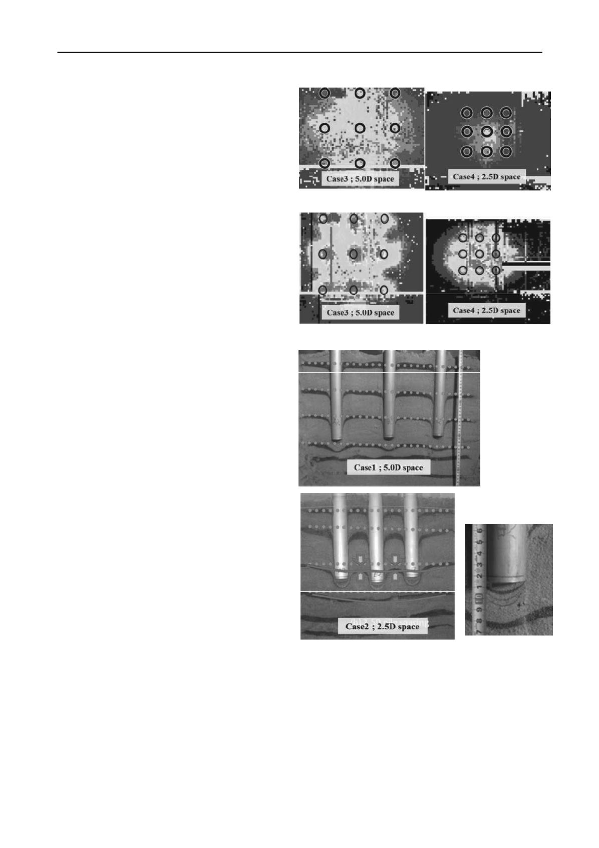
suggests the strong interaction near the pile tip incase of 2.5D
spacing.
3.4
Observed ground deformation
Figures 12 and 13 show the ground deformation after the
completion of loading tests. The colored sand layers were
installed in the horizontal direction with the equal interval prior
to model construction. The dotted lines show the initial location
of each colored sand layer. After the pile penetration of 240
mm, the distance of colored sand layers decreased to 5% of the
original distance at the maximum below the pile bottom. This
means that the ground just below the pile bottom was
compressed severely. In the compressed core, heavy particle
crushing was observed. These features occurred in both cases of
pile spacing.
In contrast, the shape of ground deformation between or
below piles was different according to the spacing. For 5.0D
spacing, the ground below each pile moved down separately.
On the other hand, in case of 2.5D space the ground under the
group pile deformed in a continuous convex way. Furthermore,
the ground between piles also moved down. This suggests that
the ground not only below the pile but also between piles was
compressed downward together in the case of 2.5D spacing.
4 CONCLUSIONS
The vertical loading tests of the group pile and the single pile
were conducted. By comparing the bearing load, stress
concentration by the pile location, pressure distribution and the
ground deformation, the following conclusions may be drawn.
(1) For the narrower 2.5D pile spacing, the group pile yields at a
larger settlement and the settlement was almost same as that
in the loading of a pile of a large diameter. In contrast the
settlement in the 5.0D pile spacing was similar to that in the
loading of a single pile of the same diameter.
(2) For 2.5D pile spacing, tip resistance concentrated to the
corner piles in the early state of loading. The concentrated
load shifted to the center pile after the settlement increased.
The same shift of the concentration occurred in the bottom
of the single pile with the larger diameter as well.
(3) The higher ground pressure occurred below the bottom of
each pile individually in 5.0D spacing group pile near the
pile bottom. In contrast, the higher pressure was observed in
a block manner and the highest pressure showed a ring
distribution in 2.5D spacing group pile.
(4) The ground only below the bottom of each pile deformed
downward individually in case of 5.0D spacing. Conversely,
the ground under the group pile deformed in a contiguous
convex curve for 2.5D spacing.
From these observations, it was concluded that individual piles
in the group pile with 5.0D spacing behaved independently. In
contrast, the group pile of 2.5D spacing behaved in a block,
similar to one large single pile.
5 ACKOWREDGEMENT
Authors are thankful to Dr. Sadao Yabuuchi, President of Japan
Pile Corporation for his invaluable support. Authors also
appreciate the discussion made by members of the research
committee on group pile that was sponsored by the Kanto
Chapter of the Japanese Geotechnical Society.
6 REFERENCES
1) Whitaker, T. : Experiments with Model Piles in Groups,
Geotechnique, Vol. 7, pp. 147-167, 1957
2) Vesic A.S. : A Study of Bearing Capacity of Deep Foundations,
Final Rep., Project B-139, Georogia Inst. of Tech., 1967
3) Itoh, A. and Yamagata, K. : Vertical Loading Test of Model Group
piles(Part 3: Influence of Pile Spacing), Proceedings of Annual
conference AIJ, Structure
Ⅰ
, pp. 661-662, 1988 (in Japanese)
4) Goto, S. Aoyama, S., Liu, B., AyalaAlarco, R., Takita, A. and
Towhata, I. : Model pile and group pile bearing capacity in large
scale soil tank test ,Proceedings of IS-Kanazawa 2012, 2012
Figure 11. Pressure distribution at 110mm distance
Figure 10. Pressure distribution at 290mm distance
Figure 12. Ground deformation
after all loading tests
Figure 13. Ground deform.
near the pile bottom


