2014
Proceedings of the 18
th
International Conference on Soil Mechanics and Geotechnical Engineering, Paris 2013
horizontal load
R
1
corresponding to area
S
1
under the reactive-
pressure curve in Fig. 4, c and the displacements
z
avg
(19).
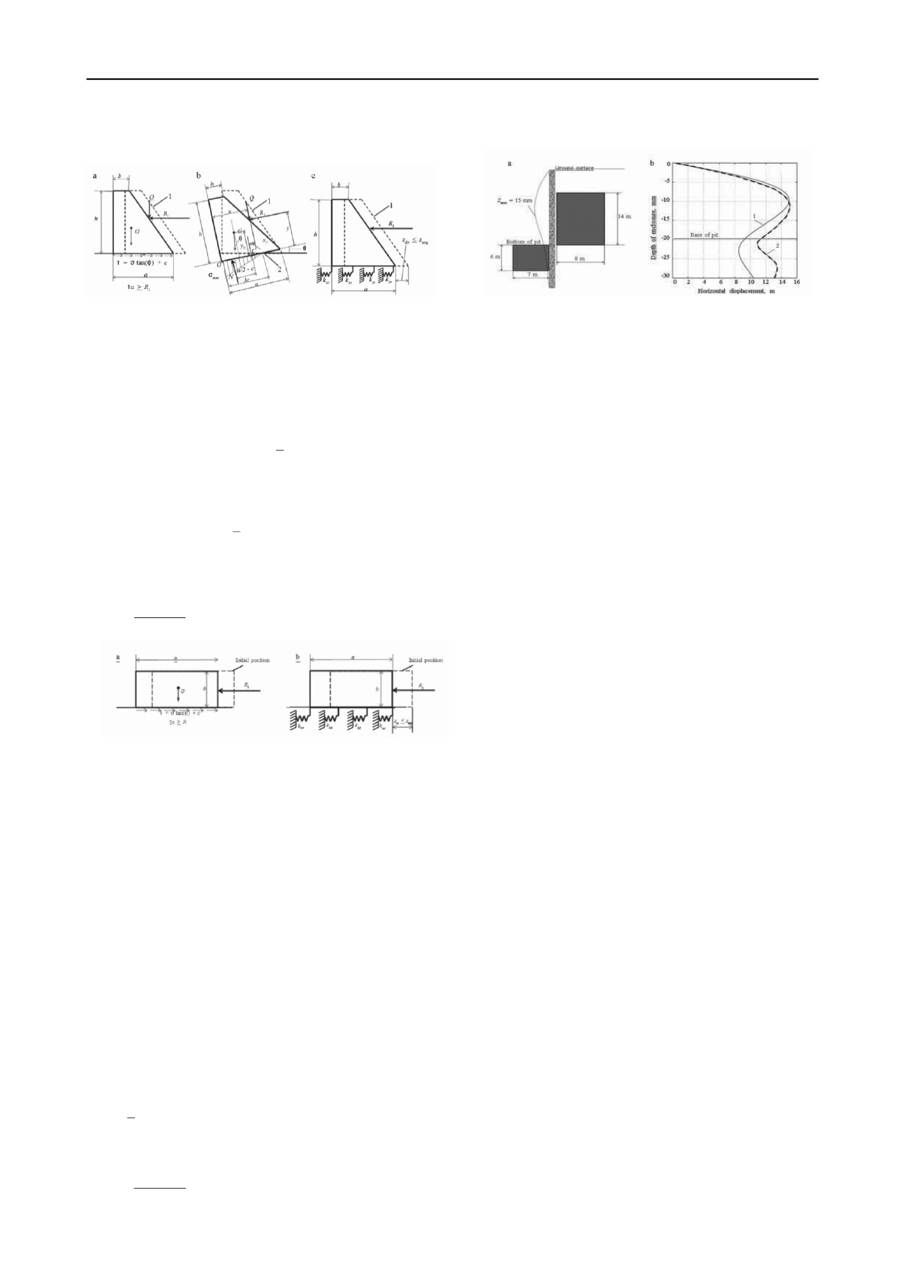
Figure 5. Computational diagrams for SCM above bottom of pit: 1)
initial position; 2) turning point.
The optimal dimensions of the SCM on the outside of the pit
were found by solving the other optimization problem which
minimize cross sectional area of the massive retaining wall
(trapezoid)
Figure 7. Results of problem solution: a) optimal SCM dimensions
when
S
max
= 15 mm; b) results of comparison: 1) elastic bed; 2)
PLAXIS 2D.
The optimal dimensions are determined for the allowable
displacement of the enclosure
S
max
= 15 mm as a result of
solution of the problems described (Fig. 7, a).
ψ 0 (
a
,
b
) = (a+b)h/2
→
min
(20)
for limits ensuring observance of the following conditions:
1) stability against shear (Fig. 5, a)
(
Q
(
a, b
) +
G
(
a, b
))tan(
ϕ
) +
ca
>
R
1 ,
(21)
where
Q
is the weight of the soil in the SCM benches;
2) stability against overturning about a certain point (Fig. 5,
b) with consideration of the deforming bed in accordance with
Klein's procedure (
Klein 1964
)
M re
(
a, b
) =
N
(
a
/2
−
c
) >
M a
(
a, b
) =
R
1
y
+
G
(
a
/2
−
x
)
−
Qx c
;
(22)
3) the displacement
z
sc
of the SCM under the action of
R
1
should not exceed the displacement
The numerical modeling was performed in the software
package PLAXIS 2D with consideration of the SCM
dimensions obtained, and plots of the horizontal displacements
were compared (Fig. 7, b). The discrepancy between the
maximum horizontal displacements was insignificant, although
the pattern of the curves differed somewhat. Similar
calculations and comparison with PLAXIS were conducted for
the same initial data, but with limits placed on the
displacements
S
max
= 30 and 60 mm. It was established that the
SCM dimensions obtained with use of the proposed method
yielded a high safety factor with respect to displacements with
increasing tolerances. Application of the method in question is
therefore restricted to the region of small enclosure
displacements; this does not contradict the goals of the stated
problem.
z
avg
averaged over the height
h
(Fig. 5, c).
;
1
ср
гр
гц
z
tgak
R
z
Figure 6.
Computational diagram for SCM below bottom of pit
If the first two stability conditions are observed, the
displacement of the SCM is determined only by the horizontal
deformation of the soil in the bed, which is described by the
stiffness coefficient
k
so
of the soil when the rotation of the mass
is disregarded.
In order for the system to function in the elastic stage, the
dimensions of the SCM below the bottom of the pit are
determined with consideration of the fact the soil takes up the
reactive pressure, and the SCM the remaining portion. Above
the point of intersection, the reactive pressure exceeds the
passive pressure of the soil
q
p
(see Fig. 4, c), but is lower than
the passive pressure below the point; the minimal height of the
SCM will therefore correspond to the distance from the bottom
of the pit to the point of intersection of the
r
and
q
p
curves.
Here, the design load on the SCM is calculated based on area
S
2
(see Fig. 4, c)
3
CONCLUSIONS
A computational method is developed for determination of
the optimal dimensions of a soil-cement mass (SCM) that
reduces the displacements of an enclosure to required
values. The method includes:
− a computerized-search algorithm for optimal engineering
of the coefficient of stiffness of an elastic bed; and,
− calculation of optimal SCM dimensions corresponding to
the optimal stiffness using standard procedures for analysis of
massive retaining walls.
The computational method makes it possible to determine
optimal SCM dimensions for the excavation of deep pits in a
dense urban setting, when it is necessary to shorten considerably
the construction time, and ensure a minimal effect of excavation
on surrounding development.
4
REFERENCES
The optimal dimensions of the SCM under the bottom of the
pit are determined by solving the optimization problem which
minimize the value of the efficiency function corresponding to
the cross-sectional area of the mass
Gotman Yu.A. 2010. Variant design of using the jet-grouting
technology for reduction of the settlements of existing buildings
during construction of an underground complex in Moscow.,
Geotechnical Engineering 20. View of Young European
Geotechnical Engineers
, Brno, 134-139.
Hogg E. and Arora Ya. 1983. Applied Optimal Design.
Mechanical
Systems and Structures
[Russian translation], Mir, Moscow.
Klein G.K. 1964.
Analysis of Retaining Walls
[in Russian], Vysshaya
Shkola, Moscow.
ψ 0 (
a, b
) =
ab
→ min
(25)
with limits ensuring observance of the following conditions:
−
the stability of the SCM against shear (Fig. 6, a)
R
2 <
F n
=
G
tan(
ϕ
) +
ca
;
(26)
−
the displacement
z
sc
of the SCM under load
R
2
is no
greater than the displacement
z
avg
averaged over height
h
(Fig.
6, b)
avg
so
sc
z
tgak
R
z
2
(27)


