2018
Proceedings of the 18
th
International Conference on Soil Mechanics and Geotechnical Engineering, Paris 2013
displacements are closer to each other, the two axial forces were
also close to the values of 35tons.
8 CONCLUSIONS
High correlation is recognized between the wall
displacements and the axial forces in the struts. In addition, the
changes of axial forces were negligible as the time elapses at the
locations where the large wall displacements are detected. This
means that the ground anchors are working quite well at such
locations (Jang et al., 2012).
In this study the displacement on the C.I.P. walls and the
axial forces on the slabs are monitored in the two excavation
sites. In the sites, two new top down methods, S.P.S & S.T.D,
are applied with the traditional support method, i.e. ground
anchor. The monitored values are analyzed and compared with
those predicted at the design stage. The conclusions obtained
are the following:
6.2 Site 2: S.T.D and C.I.P
1) The monitored displacements of C.I.P rigid walls with
S.P.S support were similar to the predicted values. The
displacement of the S.P.S support wall came from the
characteristics of the support which does not applies the
pre-stresses to the wall. The displacement of the wall is
allowed by the slab without restriction.
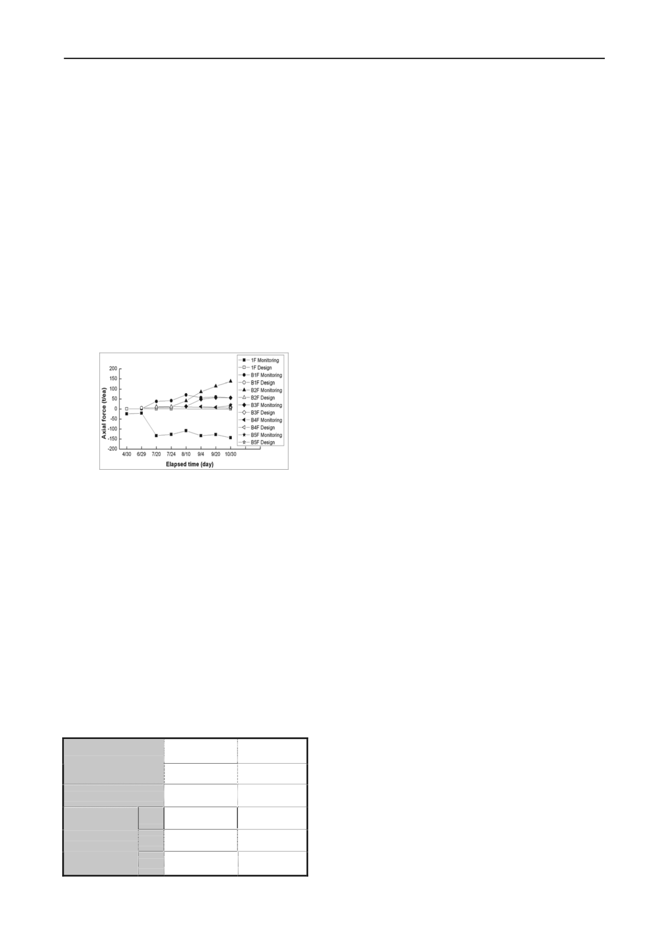
Fig. 14 shows the axial forces which act on the slab of S.T.D
method by comparing design and monitored values. The
monitored axial forces are mostly larger than the predicted
values set in the design stage. This result came from the
increased wall displacement due to over-excavation and the
characteristics of S.T.D. method.
Contrary to the direction of the soil pressures, tensile forces
are developed on the 1st anchor from the top. This may come
from the large displacement in the central part of the wall, i.e.
B2F and B3F, which gave reverse stresses on the upper part of
the wall.
2) Even though the rock layer is appeared in the shallow
depth, large displacements and axial forces are monitored
compared to the values predicted at the design stage in the
site where S.T.D. method is applied. This is because the
excavation depth is deep and the over-excavation was
made at the final stage of construction to reduce the
construction time.
3) It is necessary to reflect the characteristics of the
excavation method and the soil conditions when the
retaining walls are planned for excavation site. At the site
of excavation, the monitored value in each stage should be
reviewed and compared with the designed values.
Feedback analysis is sometimes needed when some field
problems are anticipated.
4) Quantitative inspection of the construction time of the
selected sites indentifies the significant reduction of the
construction time when the slab support methods are
applied compared with the traditional ground anchor
supports.
Figure 14. Section A-A’ Slab axial forces
7 COMPARISON OF CONSTRUCTION TIME
The current retaining wall design, which uses slab as the
support of the wall, applies S.P.S and S.T.D methods. These
methods can save the construction time because they can
support the retaining walls as well as can use the slabs as the
permanent basement structure of the building. The two sites
have different excavation area and depth. Hence a direct
comparison of the construction period was difficult. In this
study, construction period was calculated and relative
comparison was made based on the Site 1, which was quantified
by area (15,000 m2) and the excavation depth (GL.-19m).
9 ACKNOWLEDGEMENTS
Table 1shows the comparison of the construction time of the
basement for different support methods. In Site 1 where the
ground anchors are partly used, the construction time was 9
months. However, in Site 2 where the slab support S.T.D is
used, the slabs are installed simultaneously with the excavation
and the time taken to finish the basement structure was 7
months.
This research was supported by the Basic Science Research
Program through the National Research Foundation of Korea
(NRF), funded by the Ministry of Education, Science and
Technology (No.2012-0002408). This paper is also a part of the
result from the “Maintenance of Foundation Design Criteria
under the Construction Facilities for Standardization”, the
“Construction & Transportation R&D Policy and Infrastructure
Project”.
10
REFERENCES
Geogroup Eng.(2010),"SUNEX Manual, 13th Ver. 6.01. SI Version",
P1-3.
Jang ,Y. S., S.M Shin and J.H. Hoe (2012), “A Study on Design and
Construction of Earth Retaining Wall Using Multi-Supporting
System”, KGS-IGS Geotechnical Workshop, I.I.T., New Delhi,
December 12.
Table 1. Comparison of construction time for two sites
Site 1: Chung Ju Site 2 : Sang Am
Construction Method
S.P.S & Anchor
S.T.D
Excavation Depth
GL.-19m
GL.-26m
Start
2010.10
2012.04
End
2011.06
2012.11
Excavation
And Sub- structure
Period
9 month
7 month
Saegil E&C (2011a), "Hyundai Department Chung Ju Excavation
Design and Field Monitoring Report"
Saegil E&C (2011b), "SANG-AM DMC E2-3BL Excavation Design
and Field Monitoring Report"
Sho, Kwang-Ho (2011) “Study on the Application of Semi-open cut
Top-Down Construction for Framework” Journal of the Korean
Association for Spatial Structures, Vol.11, No.2, pp.129~138.


