2017
Technical Committee 207 /
Comité technique 207
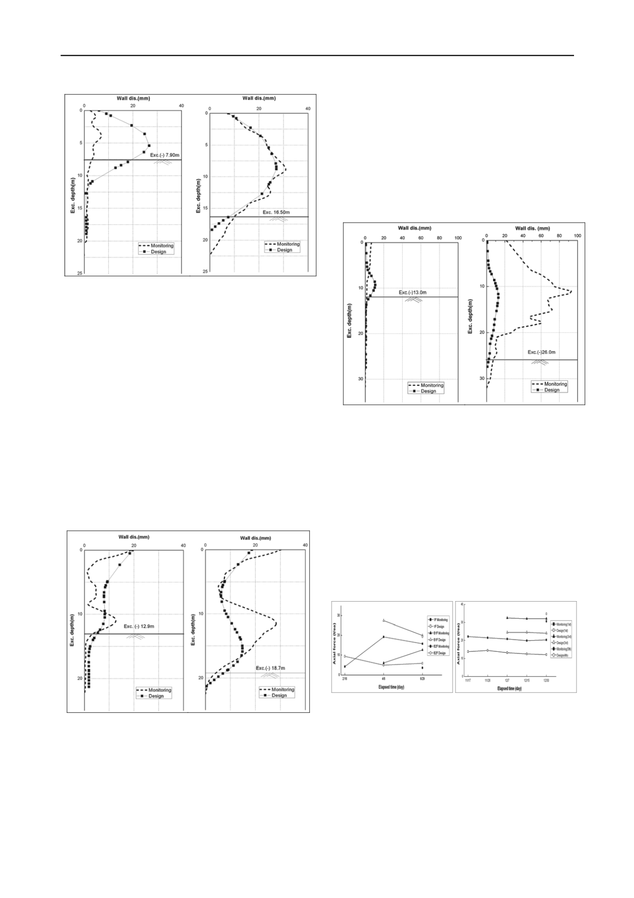
a) Mid stage (GL.-7.9m) b) final stage ((GL.-16.5m)
Figure 10. Wall displacements for S.P.S applied section
The displacements of the wall where the ground anchors are
applied are shown in Fig. 11. As can be recognized in the
figure, the predicted displacement in the mid stage was larger
than the monitored value. In the final stage, the two
displacements are consistent partly but larger displacements of
10mm are monitored at the upper and central positions of the
wall.
This large displacement seems to come from the initial over-
excavation length of more than 5m due to the sewage culvert
box near the ground surface in Fig. 5b. As the excavation went
on the final stage, the spacing of the ground anchors was about
3m and the over-excavation which was greater than the
designed strut spacing was made in the field.
Therefore, it is judged that a particular sites like this one
which has large sewage culvert box near the ground surface and
the over excavation is made near the final stage needs the
detailed design and construction considering all the factors
related to spacing of the ground anchor and strut, initial
displacement of the wall near the ground surface and the
geotechnical conditions included.
a) Mid stage (GL.-12.9m) b) final stage ((GL.-18.7m)
Figure 11. Wall displacements for ground anchor applied section
5.1.2 Site 2: S.T.D and C.I.P
Fig. 12 shows the wall displacements for mid and final stages
of excavation in the site 2 where S.T.D method is applied. The
excavation depths of mid and final excavation stages were GL.-
13.0m and GL.-26.0m, respectively. In the mid stage, the
predicted and monitored displacements came out very similar.
In the final stage, large discrepancy was recognized for the
predicted and the monitored displacements, i.e. 13mm and
93.1mm, respectively.
Proper construction process and the favorable soil conditions
near ground surface seemed to create the consistent wall
displacements in the mid stage. Large monitored wall
displacements may come from the fact that (1) The design
condition would not include the time effect of concrete curing
in the slab; (2) over excavation was made since the weathered
and soft rocks appeared in the initial stages of excavation. The
large discrepancy of the wall displacement about 80mm was the
accumulated displacement of the 26m deep excavation.
a) Mid stage (GL.-13m) b) final stage (GL.-26m)
Figure 12. Wall displacements in S.T.D method applied
6 AXIAL FORCES OF RESISTANT BODIES
6.1 Site 1 : S.P.S and ground anchor on C.I.P wall
Fig. 13a shows the predicted and monitored axial forces
acting the struts of S.P.S. The two axial forces in the initial
stage showed large difference, because the construction
conditions, e.g. ambient temperature and impacts, etc, create
large changes in the strain gages measuring the axial forces.
However, this discrepancy was reduced as the predicted and
monitored displacements became similar (see Fig. 10b).
It is necessary to indentify the wall displacements together
when the axial forces in the supports of S.P.S are analyzed.
a) S.P.S b) Ground Anchor
Figure 13 Axial forces for site 1
Fig 13b shows the axial forces of ground anchors in the
locations where the ground anchors were applied. In general,
the pre-stress considered in the design stage is sufficiently
reflected on the ground anchors constructed in the field.
However, the monitored axial forces tend to be larger than the
predicted values in the design stage in site 1, although the pre-
stresses designed are fully reflected at the excavation.
According to Fig. 11b, the axial forces were large at the
locations in which the large wall displacements are detected. At
the location of 5th floor in which the design and monitored


